
What is a Flow Conditioning Chamber
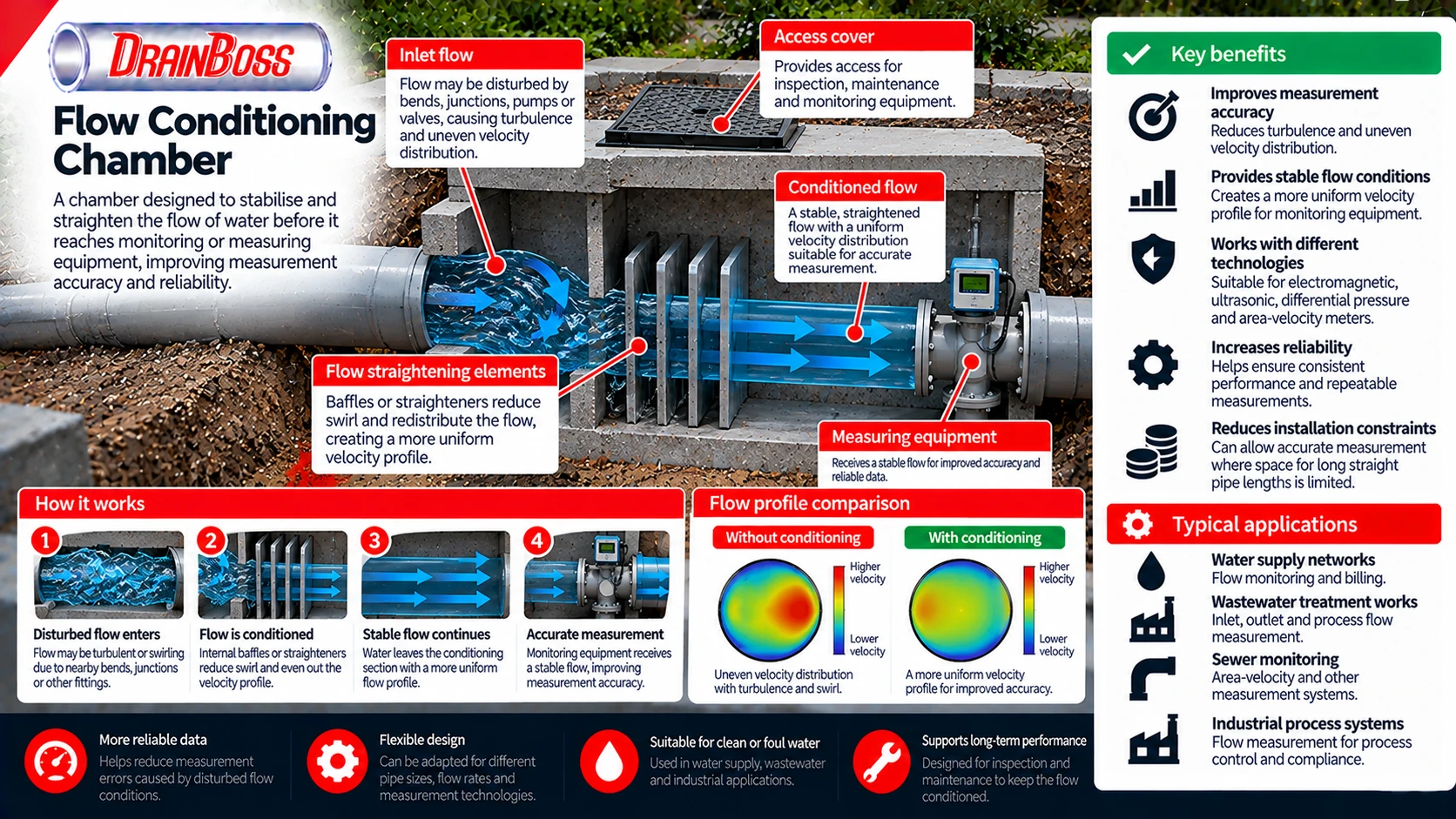
A flow conditioning chamber is a hydraulic structure designed to improve the flow conditions of water or wastewater before it reaches monitoring, sampling or measuring equipment. Its main purpose is to reduce unwanted turbulence, uneven velocity distribution, swirling flow and other disturbances that can affect measurement accuracy. Depending on the installation, the chamber may use internal baffles, flow straighteners, specially shaped channels or changes in cross-sectional geometry to produce more stable and predictable hydraulic conditions.
Flow conditioning chambers are used in water supply networks, wastewater treatment works, sewer monitoring installations and industrial process systems. They are particularly useful where measuring equipment must be installed close to bends, junctions, pumps, valves or other components that disturb the flow. Without suitable conditioning, the velocity measured at one point may not accurately represent the average velocity across the pipe or channel.
The term describes a function rather than one standardised chamber design. A flow conditioning chamber may be a separate structure containing hydraulic components, an enlarged section of a pipeline or a purpose-built monitoring chamber with integrated flow control features. The appropriate arrangement depends on whether the water flows through a full pipe, a partially filled sewer or an open channel, as well as the measurement technology being used.
Importantly, flow conditioning does not necessarily mean reducing the total discharge. A properly designed chamber aims to improve the distribution and stability of flow while allowing the required volume of water to pass through the system. Its hydraulic resistance, operating range and potential effects on upstream water levels must therefore be considered alongside measurement performance.
Why Flow Conditions Affect Measurement Accuracy
Flow measurement equipment operates on the assumption that certain hydraulic conditions are present at the measuring location. These conditions vary between technologies, but many instruments require a sufficiently stable velocity distribution or a predictable relationship between water depth and discharge.
In a straight, fully developed pipe flow, the velocity is not identical at every point across the pipe. Friction at the pipe wall reduces the local velocity, while water nearer the centre generally moves faster. The resulting velocity profile depends on the flow regime, pipe roughness and other hydraulic conditions.
When water passes through a bend, valve, junction or pump, the velocity distribution can become distorted. Some areas of the pipe may carry faster-moving water than others, and the flow may develop rotational or swirling components. These disturbances can persist downstream, particularly where the available straight pipe length is limited.
For a full pipe, the relationship between average velocity and volumetric flow rate is:
Q = A x V
Where:
-
Q is the volumetric flow rate in cubic metres per second (m3/s).
-
A is the internal cross-sectional area of the pipe in square metres (m2).
-
V is the average flow velocity in metres per second (m/s).
For example, a circular pipe with an internal diameter of 200 mm has a cross-sectional area of approximately 0.0314 m2. If the average velocity is 1.5 m/s, the corresponding flow rate is approximately 0.0471 m3/s, equivalent to 47.1 litres per second.
The calculation is straightforward when the true average velocity is known. The difficulty is that many instruments do not measure velocity uniformly across the entire cross-section. Instead, they estimate flow using measurements taken along a particular path, within a defined sensing region or at selected locations.
A distorted velocity profile can therefore introduce measurement error if the instrument’s assumptions or compensation methods do not adequately account for the actual flow conditions.
Different disturbances can affect measurement in different ways. Swirling flow introduces rotational movement, while asymmetric velocity distribution causes one part of the cross-section to carry a disproportionate share of the discharge. Pulsating flow produces changes in velocity over time, and air entrainment may interfere with certain sensing technologies.
The effects are particularly important where measurements are used for regulatory reporting, process control, billing or performance assessment. A small systematic error can become significant when flow volumes are accumulated over long periods.
A flow conditioning chamber attempts to reduce these uncertainties by creating hydraulic conditions that are more compatible with the selected measurement method.
Internal Design and Flow Conditioning Components
The internal arrangement of a flow conditioning chamber is selected according to the disturbance that must be corrected. There is no single combination of components suitable for every pipe diameter, flow rate or measuring instrument.
Some chambers use parallel flow straightening elements to reduce rotational movement. Others incorporate baffles or specially shaped passages that redistribute the flow before it reaches the measuring section.
A flow straightener is intended primarily to reduce swirl and encourage flow to move more consistently along the main axis of the pipeline. It may consist of parallel tubes, vanes or other structures that restrict unwanted transverse movement.
A flow conditioner can have a broader function. Certain engineered designs redistribute momentum across the pipe cross-section to produce a velocity profile that is more suitable for downstream measurement.
The distinction is important because removing swirl does not necessarily eliminate an uneven velocity distribution. A device may successfully reduce rotational flow while leaving substantial differences in axial velocity across the pipe.
Typical chamber components include:
-
Inlet transition. Connects the upstream pipe or channel to the conditioning section while controlling changes in flow geometry.
-
Flow straightening elements. Reduce swirl and unwanted transverse velocity components.
-
Baffles or perforated plates. Redistribute flow and may reduce particular disturbances when correctly designed.
-
Conditioning section. Provides the hydraulic arrangement needed to improve the velocity distribution.
-
Measuring section. Houses or leads towards the instrument used to measure flow.
-
Outlet transition. Returns the flow to the downstream pipe or channel without introducing unnecessary hydraulic losses.
-
Access provisions. Allow inspection, cleaning and maintenance of internal components where required.
Not every chamber contains all these features. A compact installation may use a proprietary conditioning element within a short pipe section, while a larger monitoring structure may incorporate several stages of hydraulic control.
The geometry of the inlet and outlet is important. Abrupt expansions can produce flow separation and recirculation, while poorly designed contractions may create additional turbulence. A chamber that reduces one disturbance but introduces another may fail to improve measurement performance.
Internal components also create resistance to flow. Baffles, plates and straightening elements can increase pressure loss in a closed pipeline or head loss in an open-channel system. This effect must be assessed because excessive resistance can reduce hydraulic capacity or raise upstream water levels.
For gravity drainage systems, the consequences can be particularly important during high flows. A conditioning chamber must not create an unacceptable restriction that increases the likelihood of surcharge or upstream flooding.
The internal arrangement should also account for the materials carried by the water. A chamber handling relatively clean treated water has different requirements from one receiving raw sewage containing suspended solids, fibrous waste and other debris.
Flow Conditioning for Different Measurement Technologies
The amount and type of flow conditioning required depend heavily on the measuring equipment. Instruments use different physical principles, and they do not respond identically to disturbed flow.
Electromagnetic flowmeters are widely used in conductive liquid applications, including water and wastewater. They measure flow using the voltage generated when conductive liquid moves through a magnetic field. Their accuracy can be affected by installation conditions, including velocity profile distortion, incomplete pipe filling and electrical or mechanical factors.
Manufacturers specify installation requirements for particular meter models. Some electromagnetic meters are designed to operate with relatively short straight pipe lengths, while others require more restrictive conditions. A flow conditioning chamber should not be assumed necessary simply because an electromagnetic meter is installed.
Ultrasonic flowmeters may measure the transit time of sound travelling through the liquid. The relationship between the measured acoustic signals and average flow velocity depends on the instrument design and the distribution of velocity along the measurement paths.
A distorted velocity profile can affect the representativeness of the measured paths. Multipath ultrasonic meters can improve the estimation of average velocity by sampling several regions of the flow, although their performance still depends on installation conditions and the manufacturer’s specifications.
Differential pressure flowmeters use a restriction or other primary element to establish a relationship between pressure difference and flow rate. Their performance may depend on the upstream velocity profile and the presence of swirl. Suitable conditioning can reduce installation-related uncertainty where the relevant measurement standard or manufacturer permits its use.
In partially filled sewers, area-velocity instruments estimate discharge using measured water depth and velocity. Their performance depends on the relationship between the local velocity measurement and the average velocity across the wetted section.
A conditioning chamber may help where the upstream approach flow is irregular, but it cannot automatically correct every source of uncertainty. Changes in water level, sediment deposits, downstream backwater and irregular channel geometry may still affect measurement.
The following table compares common measurement arrangements.
| Measurement technology | Typical application | Sensitivity to flow conditions | Potential role of conditioning |
|---|---|---|---|
| Electromagnetic flowmeter | Full-pipe water and wastewater measurement | May be affected by disturbed velocity profiles and installation conditions | Improve approach flow where required by the meter specification |
| Transit-time ultrasonic meter | Full-pipe flow measurement | Velocity profile and swirl can influence path-based measurements | Reduce profile distortion and rotational flow |
| Differential pressure meter | Pressurised pipe systems | Often requires defined upstream flow conditions | Provide suitable approach conditions where permitted by the relevant standard |
| Area-velocity meter | Partially filled sewers and channels | Sensitive to local velocity distribution and hydraulic conditions | Improve flow uniformity where the chamber design supports it |
| Flume or weir | Open-channel flow measurement | Requires suitable approach flow and hydraulic conditions | Establish a more consistent approach to the primary measuring structure |
| Mechanical velocity meter | Selected water and process applications | May be affected by swirl and non-uniform velocity | Improve the flow profile within the instrument’s operating requirements |
These are general characteristics rather than universal installation rules. The appropriate upstream and downstream straight lengths, conditioning devices and operating limits must be established for the specific instrument.
A chamber designed around one meter type may not be suitable for another. For example, a flow straightener that improves the performance of a particular full-pipe instrument may not provide the water-level conditions required for an open-channel flume.
Measurement technology should therefore be selected before the final conditioning arrangement is designed.
Flow Conditioning in Sewers and Open Channels
Flow conditioning in gravity sewers presents different challenges from conditioning in pressurised pipelines. A sewer may operate partially full during normal conditions and become surcharged during heavy rainfall or peak wastewater flows. Its hydraulic behaviour can therefore change substantially across the operating range.
In a partially filled sewer, discharge depends on both the wetted cross-sectional area and the average velocity. Changes in water depth alter the area available for flow, while channel gradient, roughness and downstream conditions influence velocity.
An open-channel monitoring chamber may be designed to provide a stable measuring section with a consistent cross-sectional geometry. The intention is to reduce local disturbances and improve the reliability of water-level and velocity measurements.
However, the chamber must also accommodate the solids and debris normally present in wastewater. Internal features that are suitable for clean water may trap wipes, rags, sediment or other material in a foul sewer.
For this reason, conventional baffle arrangements are not always appropriate for raw wastewater applications. The design must balance hydraulic conditioning against the risk of obstruction and the need for maintenance.
In open-channel measurement, approach conditions are particularly important for flumes and weirs. These structures establish a relationship between flow rate and water level under defined hydraulic conditions.
A flume typically uses a shaped channel section to create a predictable hydraulic relationship. The upstream approach should allow water to enter the structure without excessive turbulence, asymmetric flow or other disturbances that compromise the intended measurement conditions.
A weir measures flow using the relationship between water level and discharge over a defined crest. Its performance depends on factors such as crest geometry, approach conditions and downstream water levels.
Where downstream water levels interfere with the intended hydraulic control, measurement accuracy may be reduced. Flow conditioning upstream does not necessarily resolve this problem because it originates from the downstream boundary conditions.
Sewer monitoring installations can also be affected by sediment deposition. Accumulated material changes the effective channel geometry and may interfere with sensors or alter the local velocity distribution.
A chamber that provides good measurement conditions immediately after installation may therefore perform differently after prolonged operation if sediment is allowed to accumulate.
The design should consider whether the selected geometry encourages self-cleansing flow or creates low-velocity zones where material can settle. In some cases, a conventional monitoring chamber with carefully selected sensor positioning may be more suitable than a complex structure containing additional hydraulic components.
Designing a Chamber for the Expected Flow Range
A flow conditioning chamber must operate across the range of flows expected at the installation. Designing only for the maximum flow rate can result in poor performance during normal or low-flow conditions, particularly in gravity drainage systems.
In water supply and industrial pipelines, the operating range may be relatively well defined by pumps, valves and process requirements. In stormwater and combined sewer systems, flow can vary much more substantially between dry weather and intense rainfall.
The design process should begin with the hydraulic conditions at the proposed location. These include the expected discharge range, pipe or channel dimensions, upstream disturbances, downstream water levels and the operating requirements of the measuring instrument.
Important design parameters include:
-
Minimum, normal and maximum expected flow rates.
-
Pipe diameter or channel cross-sectional geometry.
-
Velocity distribution and potential swirl at the inlet.
-
Available straight length before and after the measuring location.
-
Pressure loss or head loss introduced by the chamber.
-
Risk of sediment deposition and debris accumulation.
-
Required measurement accuracy and operating range.
-
Access for inspection, calibration and maintenance.
The available installation space can strongly influence the selected arrangement. A meter installed immediately downstream of a bend may require a different solution from one located within a long straight pipeline.
Some proprietary flow conditioners are designed to reduce the straight lengths required by particular measurement systems. However, the permitted installation arrangement should be supported by the relevant product documentation or measurement standard.
The chamber dimensions must also be compatible with the hydraulic capacity of the system. Increasing the cross-sectional area may reduce average velocity, but an abrupt expansion can introduce recirculation zones. Similarly, a restricted passage may improve a particular flow characteristic while creating unacceptable head loss.
In pressurised systems, the additional pressure loss affects the energy required to transport water. Where pumping is involved, this can influence operating costs and the available pressure at downstream equipment.
For gravity systems, head loss may raise the upstream water level. The effect becomes particularly important where the drainage network has limited spare capacity or where downstream conditions already cause backwater.
The chamber should also avoid introducing air-related measurement problems. In full-pipe systems, air pockets can interfere with some measurement technologies, while certain installation positions may increase the likelihood of air accumulation.
The final arrangement must therefore satisfy both hydraulic and measurement requirements. Improving the flow profile is of limited value if the chamber creates unacceptable operating conditions elsewhere in the pipeline.
Verification, Maintenance and Measurement Reliability
The performance of a flow conditioning chamber should be verified as part of the complete measuring installation. The presence of baffles or flow straighteners does not, by itself, demonstrate that the required measurement conditions have been achieved.
Verification may involve reviewing the chamber geometry, checking the installation against manufacturer requirements and assessing the measuring instrument under representative operating conditions. For critical installations, additional commissioning tests or specialist hydraulic assessment may be appropriate.
Measurement uncertainty should be considered at the system level. Even where the flow profile is well conditioned, errors can arise from sensor calibration, incorrect pipe dimensions, installation geometry, electrical interference, sediment deposits or changes in operating conditions.
For example, an electromagnetic flowmeter may produce unreliable results if the pipe is not completely filled, even when the upstream velocity distribution is relatively uniform. Similarly, an area-velocity meter may be affected by an incorrect channel profile or unsuitable sensor positioning.
Maintenance requirements depend on the water quality and the chamber’s internal construction. Clean water installations may experience relatively little solids accumulation, while wastewater chambers can be exposed to sediment, grease, fibrous waste and other debris.
Internal flow straighteners and baffles may create surfaces where material can accumulate. If these components become partially obstructed, the hydraulic conditions may change and the chamber may no longer perform as originally intended.
Inspection should therefore focus on both physical condition and measurement performance. Unexpected changes in recorded flow may indicate a genuine hydraulic event, but they may also result from sensor problems, altered flow conditions or obstruction within the chamber.
Where the chamber is installed in a sewer or other confined structure, access must be managed according to the applicable safety requirements. Wastewater environments may contain hazardous atmospheres, biological contaminants and sudden changes in flow. Inspection and cleaning arrangements should be considered during the design rather than left to be resolved after installation.
Instruments used for regulatory reporting or other critical purposes may require documented calibration and verification procedures. The conditioning chamber should not prevent access to the equipment or interfere with the methods used to establish measurement accuracy.
A well-designed flow conditioning chamber provides a more predictable hydraulic environment for downstream measuring equipment. Its effectiveness depends on matching the internal geometry to the actual flow disturbance, the selected instrument and the operating conditions of the pipeline. Where these factors are properly assessed, flow conditioning can reduce installation-related measurement uncertainty without unnecessarily restricting the drainage or water conveyance system.