
What is a Drainage Layout Plan
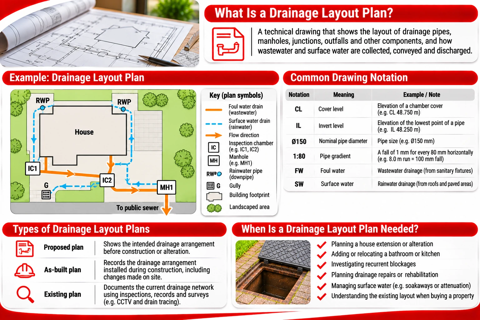
A drainage layout plan is a technical drawing that shows how wastewater and surface water are collected, conveyed and discharged from a property or site. It identifies the positions and routes of drainage pipes, inspection chambers, manholes, junctions, gullies, outfalls and other components, allowing engineers, contractors and property owners to understand how the drainage network is arranged. Depending on its purpose, the plan may also record pipe diameters, invert levels, gradients, flow directions and connections to public sewers or other drainage systems.
In the UK, drainage layout plans are used during building design, construction, property alterations, drainage investigations and maintenance. They are particularly important where underground pipes cannot be examined directly or where proposed building work could affect existing drainage infrastructure. However, a drawing prepared before construction does not necessarily represent the system as installed. Understanding the difference between proposed, as-built and surveyed drainage plans is essential when relying on them for engineering decisions.
What Information Does a Drainage Layout Plan Show?
A drainage layout plan provides a spatial representation of the drainage network, usually viewed from above. It shows how individual drainage connections combine into larger pipe runs and where the collected water ultimately discharges. A well-prepared plan should allow someone unfamiliar with the site to trace the route from a sanitary appliance, roof outlet or surface water collection point to the appropriate downstream connection.
The level of detail depends on the type of project. A domestic drainage plan may show the underground pipes serving a house, the location of inspection chambers and the connection to the sewer. A commercial development or housing estate may require a much more detailed drawing, including pipe schedules, manhole references, levels, attenuation features and separate foul and surface water networks.
Common components recorded on drainage layout drawings include:
-
Foul drainage pipes. Pipe runs carrying wastewater from toilets, sinks, showers, kitchens and other connected sanitary appliances.
-
Surface water drains. Pipes collecting rainwater from roofs, paved areas and other drainage surfaces.
-
Inspection chambers and manholes. Access points used for inspection, cleaning and maintenance, identified by location and often by a reference number.
-
Pipe junctions. Connections where branch drains join larger pipes or where separate drainage runs meet.
-
Gullies and drainage channels. Collection points receiving surface water or wastewater from appropriate fixtures.
-
Soil and vent pipes. Vertical drainage and ventilation components, where relevant to the drawing’s scope.
-
Outfalls and discharge points. Locations where drainage systems discharge into sewers, watercourses, soakaways or other approved destinations.
-
Drainage control features. Components such as non-return valves, interceptors, pumping chambers and flow control devices where installed.
-
Sustainable drainage features. Soakaways, attenuation tanks, permeable drainage arrangements and other surface water management components.
The drawing should distinguish between foul water and surface water systems wherever they are separate. This is important because connecting rainwater drainage to a foul sewer, or wastewater drainage to a surface water system, can create operational and environmental problems. A combined drainage system may carry both flows within the same network, but this arrangement must be correctly identified rather than assumed.
Pipe routes are generally represented by lines, with symbols indicating access chambers, gullies and other fittings. Flow direction arrows help identify which way water travels through the network. Where multiple pipes intersect on a drawing, additional notation may be needed to distinguish a physical connection from pipes crossing at different levels.
A drainage layout plan also needs a scale, orientation and sufficient reference information to establish the position of its components. Drawings for building projects are commonly produced at scales such as 1:100, 1:200 or 1:500, depending on the site size and required detail. These are examples rather than mandatory scales, and the selected scale must allow the relevant features to be read clearly.
How to Read Pipe Levels, Gradients and Drainage Symbols
A drainage layout drawing becomes considerably more useful when it includes vertical information. Pipe positions alone do not establish whether wastewater can flow by gravity, whether two connections are at compatible levels or whether a proposed extension can connect to the existing system.
The most important measurements are invert levels, pipe diameters and gradients. Together, they help establish the intended hydraulic arrangement and the available depth for drainage connections.
An invert level is the elevation of the lowest internal point of a pipe at a specified location. It is commonly expressed in metres relative to a stated datum. For example, an invert level of 48.250 m indicates the pipe invert elevation relative to that datum, not a depth of 48.250 m below the ground.
A cover level, often abbreviated CL, records the elevation of a chamber cover or another specified surface reference. The difference between the cover level and the invert level provides an indication of the vertical distance to the pipe invert, although it should not automatically be treated as the depth of the entire chamber or the depth of cover above the pipe crown.
The following table explains common information found on UK drainage layout plans.
| Drawing notation | Meaning | Why it matters |
|---|---|---|
| CL | Cover level | Indicates the elevation of a chamber cover or specified surface point |
| IL | Invert level | Identifies the elevation of the lowest internal point of a pipe or channel |
| Ø150 | Nominal pipe diameter of 150 mm | Helps identify the specified pipe size |
| 1:80 | Pipe gradient | Indicates a fall of one unit vertically for every 80 units horizontally |
| IC | Inspection chamber | Identifies a drainage access point |
| MH | Manhole | Identifies a chamber providing access to the drainage network |
| FW | Foul water | Distinguishes wastewater drainage from surface water drainage |
| SW | Surface water | Identifies rainwater drainage and associated infrastructure |
| Flow arrow | Intended direction of flow | Helps trace the downstream route |
| Outfall | Final discharge location | Identifies where the drainage system releases its flow |
Abbreviations and symbols are not entirely uniform across all drawings. Engineers and contractors may use project-specific conventions, so the drawing legend and notes should always be consulted before interpreting unfamiliar symbols.
Pipe gradients are particularly important for gravity drainage. A gradient of 1:80 means that a pipe falls 1 mm vertically for every 80 mm of horizontal distance. Over a horizontal distance of 8 m, this corresponds to a fall of 100 mm.
For example, consider an underground drain with a horizontal length of 8,000 mm and a specified gradient of 1:80. Dividing 8,000 by 80 gives a required fall of 100 mm between the two ends of the pipe. If the upstream invert level is 48.250 m, the downstream invert level would be 48.150 m, assuming the pipe maintains the specified gradient throughout that section.
This calculation describes the intended geometric fall. It does not, by itself, demonstrate that a pipe has sufficient hydraulic capacity or meets all relevant design requirements. Suitable gradients depend on pipe size, discharge characteristics, design flow and applicable guidance.
In England, Approved Document H provides guidance relating to drainage and waste disposal under the Building Regulations. Requirements and guidance can differ across the UK’s devolved nations, and relevant British Standards or project specifications may also apply. A drainage plan should therefore be assessed against the requirements applicable to its location and intended use.
Where levels are included, the drawing should identify the datum used. Comparing levels from different plans without confirming that they share the same reference can lead to serious errors in connection depths and proposed pipe gradients.
Proposed, As-Built and Existing Drainage Layout Plans
Not every drainage layout plan represents the same stage of a drainage system’s life. The distinction between design drawings, construction records and existing-system surveys is important because each provides a different level of evidence about the actual pipe arrangement.
A proposed drainage layout plan shows how the drainage system is intended to be constructed. It is normally prepared during the design process and may be revised as engineering decisions, site conditions or approval requirements change. Proposed drawings are useful for assessing the feasibility of the drainage design, but they cannot confirm that the work has been installed exactly as shown.
An as-built drainage layout plan records the arrangement installed during construction, ideally incorporating changes made on site. For example, a chamber may have been relocated to avoid an obstruction, or a pipe route may have been adjusted to accommodate existing foundations. Accurate as-built information should record such changes rather than simply reproduce the original design.
An existing drainage layout plan, sometimes prepared following a drainage survey, attempts to document the drainage network already present at a property. This may involve tracing accessible pipes, examining inspection chambers, reviewing previous drawings and carrying out CCTV investigations. The resulting plan should distinguish confirmed information from estimated routes or connections that could not be verified.
The main differences are:
-
Proposed plan. Shows the intended drainage arrangement before installation or modification.
-
As-built plan. Records the drainage arrangement installed during construction, based on the available construction records and verification.
-
Existing-system survey plan. Documents the current drainage network using observations, investigations and available records.
-
Record drawing. Provides a maintained record of the drainage infrastructure, although its accuracy depends on how thoroughly changes have been documented.
These categories can overlap in practice, and drawing titles are not always used consistently. The important question is how the information was obtained and whether the plan reflects the actual system.
Older properties present particular challenges. Drainage systems may have been extended or altered several times, sometimes without corresponding updates to the drawings. A former outside toilet, relocated kitchen or additional bathroom may have introduced connections that are absent from the available plans.
Underground pipes can also follow routes that are difficult to predict from the building layout. Historic repairs may have introduced bends, replacement sections or additional chambers, while abandoned drainage runs may remain beneath the site.
For these reasons, an existing drainage plan should not be treated as a guarantee of underground conditions. Where accurate locations are essential for excavation, construction or repair, the relevant features should be verified using appropriate survey methods.
How Is an Existing Drainage Layout Plan Produced?
Preparing a drainage layout plan for an existing property usually involves combining information from several sources. No single investigation method can reliably establish every pipe route, connection, depth and discharge point, particularly where parts of the network are inaccessible.
The process normally begins with available records. These may include building drawings, previous drainage surveys, construction documents and information from the relevant sewerage undertaker. Such records can help establish likely connections and identify public sewer infrastructure, but their accuracy and completeness must be assessed.
A site investigation then checks accessible drainage features and traces the system where possible. Inspection chamber locations, pipe entries and exits, flow directions and visible connections can provide important evidence about the underground network.
A typical drainage mapping investigation may involve:
-
Reviewing existing drawings and records to identify known or suspected drainage routes.
-
Locating accessible inspection chambers, manholes, gullies and drainage outlets.
-
Recording chamber positions and identifying the pipes entering and leaving each chamber.
-
Measuring relevant pipe diameters and invert levels where access and conditions permit.
-
Using CCTV equipment to investigate concealed pipe sections and identify junctions.
-
Using suitable locating equipment to trace camera sondes or other detectable features where necessary.
-
Checking selected connections using controlled water or dye testing when their destination is uncertain.
-
Preparing the plan and marking any unverified connections or inaccessible sections.
CCTV inspection is valuable because it allows the engineer to examine the internal route of a pipe. A camera may reveal bends, junctions, changes in material and other features that are not apparent from surface observations. However, the camera image alone does not provide a precise geographical position for the entire pipe.
A sonde, which is a small transmitter fitted to suitable inspection equipment, can help locate particular points along an underground drain when used with a compatible receiver. The accuracy of the location depends on equipment, depth, site conditions and correct operation. The resulting measurements should be recorded with an appropriate indication of their reliability.
Drain tracing may also involve specialist surveying techniques, but buried services, reinforcement, ground conditions and access limitations can affect results. A plan should not imply a level of positional accuracy that the investigation has not achieved.
When measuring levels, the engineer needs a consistent reference. For detailed construction or engineering work, chamber cover levels and pipe invert levels may be surveyed relative to an established datum. This allows the drainage network to be assessed alongside site levels, proposed foundations and other infrastructure.
An important limitation is that some connections cannot be confirmed without additional access or investigation. For example, a pipe disappearing beneath a building may connect to a known chamber, but its exact route may remain uncertain. A professional plan should show that uncertainty rather than presenting the assumed connection as a verified fact.
When Is a Drainage Layout Plan Needed?
A drainage layout plan is particularly useful when work could affect underground drainage infrastructure. It helps establish where pipes are likely to be located, which sections may be disturbed and whether the existing system can accommodate a proposed change.
During a house extension, the plan can identify drains running beneath or near the proposed foundations. This is important because building over or close to an existing drain may introduce access, structural and approval considerations. Where a public sewer is involved, the relevant sewerage undertaker may need to be consulted, and a build-over agreement or other approval may be required depending on the circumstances.
A plan is also useful when adding a bathroom, relocating a kitchen or converting a property. These alterations may require new drainage connections, and the existing pipe levels can determine whether gravity discharge is feasible. If the proposed connection is too low relative to the receiving drain, a different drainage arrangement may be necessary.
Other practical applications include:
-
Drainage repairs. Identifying access points, affected pipe runs and suitable locations for excavation or rehabilitation.
-
Recurrent blockages. Understanding how several drainage branches connect and where restrictions may affect multiple fixtures.
-
Property purchases. Supporting investigations into the condition, location and ownership of drainage infrastructure.
-
Construction planning. Reducing the risk of damaging underground drains during excavation and foundation work.
-
Drainage maintenance. Identifying chambers and pipe sections that require inspection or cleaning.
-
Surface water management. Establishing where rainwater is collected and how it is discharged or managed on site.
-
Drainage alterations. Assessing proposed connections, diversions and changes to the existing network.
Drainage ownership and responsibility are also relevant. In England and Wales, many lateral drains and sewers serving properties are owned by the statutory sewerage undertaker, although the precise position depends on the drainage arrangement and applicable legislation. Scotland and Northern Ireland have different arrangements, so ownership should not be inferred solely from the pipe’s position on a drawing.
A drainage layout plan can show where a pipe runs, but it does not necessarily establish legal ownership, easements or maintenance responsibility. These matters may require separate records and confirmation from the relevant organisations.
The plan also has limitations when assessing drainage condition. It may identify a pipe as 150 mm in diameter and show its intended gradient, but this does not establish whether the pipe is cracked, obstructed or structurally sound. CCTV inspection, testing or other investigations may be required to determine its actual condition.
Similarly, a plan showing a soakaway does not prove that the ground has sufficient infiltration capacity or that the installation meets current requirements. Surface water drainage design may require ground investigation, infiltration testing and hydraulic calculations, depending on the project.
For building projects, the drawing should be sufficiently detailed to support the decisions being made. A simple sketch may help a homeowner understand the approximate drainage arrangement, but construction work may require dimensioned drawings, surveyed levels and coordinated engineering information.
A reliable drainage layout plan is therefore more than a map of underground pipes. It provides a record of how drainage components connect, the levels at which they operate and the routes through which wastewater and surface water leave a site. Its value depends on the accuracy of the underlying information, the clarity of the drawing and the distinction between verified features and assumptions. When properly prepared and kept up to date, it supports safer construction, more efficient maintenance and better-informed decisions about drainage repairs and alterations.