
What is a Drop Inlet
A drop inlet is a surface water drainage structure designed to collect rainwater runoff from roads, car parks, paved areas and other impermeable surfaces. Water enters through an opening at ground level and is directed into an underground drainage system. Drop inlets help prevent excessive surface water accumulation by transferring runoff from the surface into pipes, chambers or other drainage infrastructure.
The term is commonly used in American drainage engineering. In the United Kingdom, comparable structures are more often described as road gullies, surface water gullies, grated inlets or catchpits, depending on their construction and function. These terms are not always interchangeable, as different inlet designs may include sediment traps, water seals or other features.
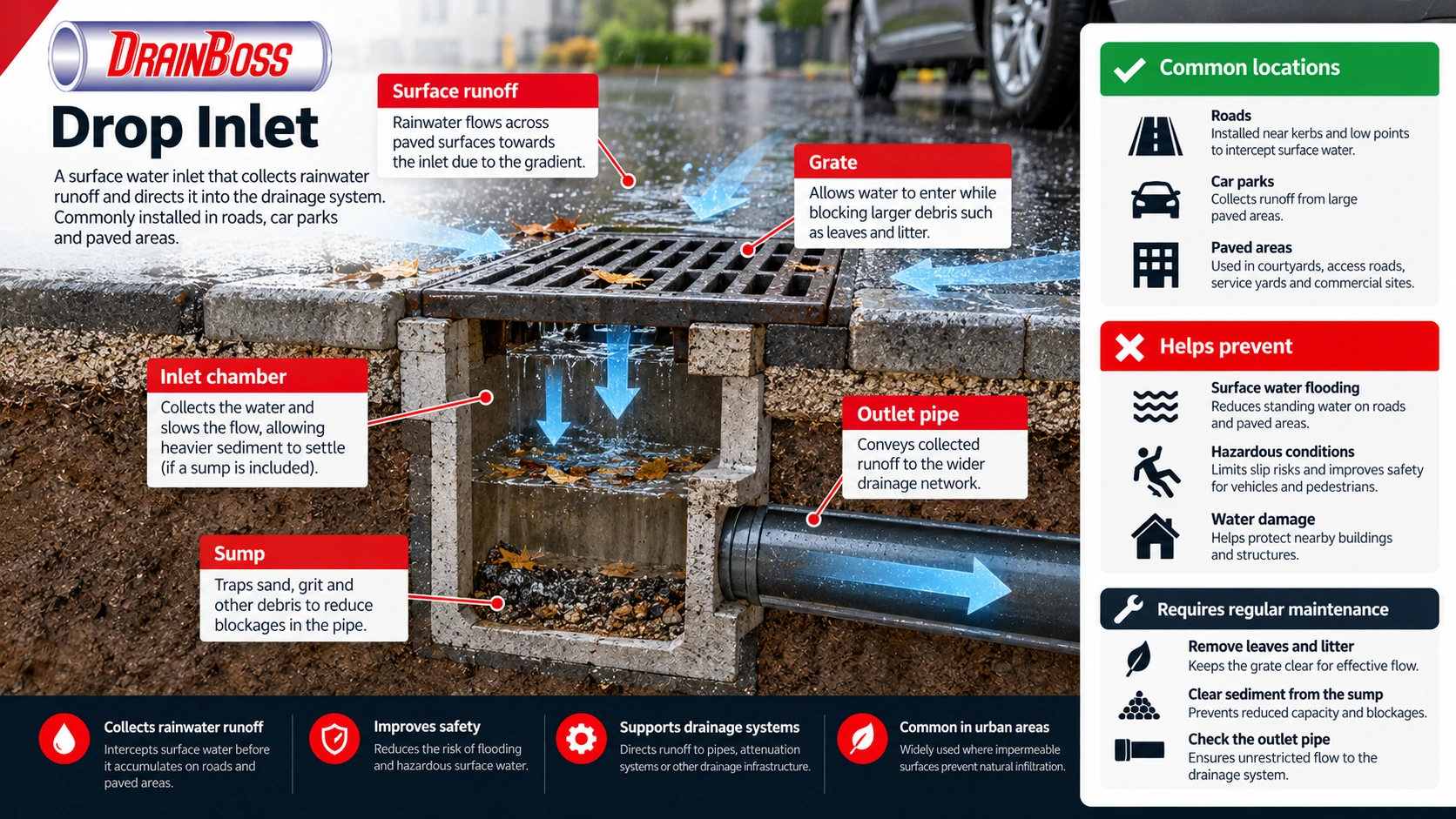
A typical drop inlet consists of a surface opening, a grate or cover, a chamber and an outlet connection. Water flows towards the inlet under gravity, enters the chamber and continues through the connected drainage network. Some designs incorporate a sump beneath the outlet to retain sediment and debris before they reach downstream pipes.
Drop inlets are particularly important in urban environments, where asphalt, concrete and other impermeable surfaces limit natural infiltration. Their effectiveness depends on correct positioning, sufficient inlet capacity, appropriate pipe connections and regular maintenance.
How a Drop Inlet Works
A drop inlet operates by collecting surface runoff at a point where water naturally concentrates. During rainfall, water moves across paved surfaces according to the local gradient. The inlet is positioned to intercept this flow before it accumulates to an unacceptable depth or reaches vulnerable areas.
On roads, drop inlets are commonly located near kerbs, at low points or along sections where runoff concentrates. In car parks and paved courtyards, they may be installed within local depressions or at the intersection of several surface gradients.
The operating process involves several stages:
-
Surface runoff flows towards the inlet as rainfall exceeds the amount that can infiltrate, evaporate or otherwise be retained on the surface.
-
Water enters through a grate, kerb opening or another suitable inlet arrangement.
-
The flow passes into a collection chamber, where some heavier sediment may settle if the design includes a sump.
-
Water exits through an outlet pipe connected to the surface water drainage network.
-
The downstream system conveys the collected runoff towards an appropriate discharge point, storage facility or treatment arrangement.
The movement of water normally relies on gravity. The inlet must therefore be installed at an appropriate level relative to the surrounding pavement and the connected drainage pipework.
In a conventional grated inlet, the grate performs two functions. It allows water to enter while limiting the passage of larger objects, such as stones and litter. However, leaves, sediment and smaller debris can still pass through the openings or accumulate on the grate.
Some drop inlets include a chamber below the outlet connection. This provides space for heavier material to settle before water enters the downstream pipe. The arrangement can reduce the amount of sediment transported through the drainage network, although it does not eliminate the need for cleaning.
The hydraulic performance of an inlet changes with the depth and velocity of approaching water. At relatively shallow depths, flow through a grate may behave similarly to flow over a weir. When the grate becomes submerged, the inlet can behave more like an orifice. The actual performance depends on the grate geometry, water depth and surrounding surface conditions.
An inlet may also operate under different conditions depending on its position. A structure installed on a continuous road gradient intercepts only part of the approaching flow, with some water potentially continuing downstream. An inlet at a local low point may collect water from several directions, but it can also become submerged if its capacity is exceeded.
Main Components and Types of Drop Inlets
Although drop inlet designs vary, most include several basic components that work together to collect and convey surface water.
The surface opening is the first point of contact with runoff. Its dimensions and configuration determine how easily water can enter the structure. A grate is commonly used in pedestrian and vehicle areas, while some road drainage arrangements use openings within or alongside the kerb.
Beneath the opening is a chamber, usually constructed from concrete, precast units or another material suitable for the installation. The chamber connects the surface opening to the underground drainage system and may provide space for sediment collection.
The outlet pipe carries collected water away from the inlet. Its diameter, gradient and downstream conditions influence how much flow can be conveyed. Even a large inlet opening will not perform adequately if the connected pipe is undersized or obstructed.
The main types of surface water inlets include the following.
| Inlet type | Construction | Typical application |
|---|---|---|
| Grated drop inlet | Horizontal grate above a collection chamber | Car parks, paved areas and road low points |
| Kerb inlet | Opening in the kerb face that intercepts gutter flow | Roads and urban streets |
| Combination inlet | Grate combined with a kerb opening | Road drainage where additional interception capacity is required |
| Sumped inlet | Collection chamber with sediment storage below the outlet | Areas where sediment accumulation is expected |
| Yard or area drain | Small grated inlet connected to underground drainage | Courtyards, service yards and paved external areas |
| Road gully | Surface inlet, commonly incorporating a sump and sometimes a water seal | UK highway drainage systems |
The distinction between these structures is important. A grated drop inlet describes the arrangement used to admit water, while a sumped inlet describes a feature of the chamber. A single installation may therefore combine both characteristics.
In the UK, road gullies are frequently used to collect surface water from carriageways. Many traditional designs incorporate a sump that retains sediment and a trapped outlet arrangement that can limit the passage of odours from connected systems. Other highway drainage designs may use untrapped chambers or different configurations.
The presence of a grate does not necessarily mean the inlet contains a sediment trap. Some surface water inlets discharge directly into a pipe connection with little or no storage space below the outlet.
Materials must also be selected according to the intended use. Covers and grates installed in trafficked areas require suitable load resistance. BS EN 124 provides classifications for access covers and gully tops according to their installation environment.
Common load classes include B125 for certain pedestrian areas and car parks, C250 for relevant kerbside applications and D400 for carriageways used by road vehicles. These classifications correspond to test loads of 125 kN, 250 kN and 400 kN respectively. The correct class depends on the precise location and applicable installation requirements.
Drop Inlet Placement and Drainage Capacity
Correct positioning is one of the most important aspects of drop inlet design. An inlet installed away from the natural path of surface runoff may collect very little water, even if it has a large opening and an adequate outlet pipe.
Drainage engineers assess the surface levels, contributing catchment area, rainfall conditions and intended flow routes before determining inlet locations. On paved sites, relatively small differences in level can change the direction in which water travels.
A road with a continuous longitudinal gradient generally conveys runoff along the kerb towards downstream collection points. Where the road forms a sag or local depression, water can accumulate from both directions. Inlets at these locations may require particular attention because there may be no convenient surface escape route if the drainage system becomes overwhelmed.
Car parks present different challenges. Large paved areas may drain towards several local low points, and vehicle movements can introduce sediment, litter and other debris. Inlet positions should avoid creating unnecessary obstructions while allowing maintenance access.
Several factors influence the hydraulic capacity of a drop inlet:
-
Contributing catchment area. Larger paved areas generally produce greater runoff volumes during rainfall.
-
Rainfall intensity. Short, intense storms can generate high peak flows even where the total rainfall depth is relatively modest.
-
Surface gradient. The slope affects runoff velocity, flow depth and the amount of water reaching the inlet.
-
Grate dimensions. The size, shape and arrangement of openings influence the rate at which water can enter.
-
Inlet location. An inlet on a continuous gradient behaves differently from one installed at a low point.
-
Debris accumulation. Leaves, litter and sediment can reduce the effective opening area.
-
Outlet capacity. The connected pipe and downstream drainage system must be able to convey the collected flow.
-
Downstream water levels. Surcharged pipes or high receiving-water levels can restrict discharge from the inlet.
A simple runoff calculation illustrates why catchment size matters. Using the Rational Method, peak runoff can be estimated from rainfall intensity, contributing area and a runoff coefficient.
For example, consider a paved area of 1,000 m² with a runoff coefficient of 0.9 and an assumed rainfall intensity of 50 mm per hour. The estimated peak runoff would be approximately 12.5 litres per second.
This is an illustrative calculation rather than a complete drainage design. Actual sizing requires appropriate rainfall data, an assessment of time of concentration, hydraulic performance and any applicable design standards.
The inlet opening and outlet pipe must be considered together. Increasing the size of the grate will not necessarily improve drainage if the downstream system cannot accept additional flow.
Similarly, a large underground pipe does not guarantee effective collection if water bypasses the inlet because of its position or grate arrangement.
For UK developments, surface water drainage design may be informed by BS EN 752, BS EN 16933 and relevant local drainage requirements. Sustainable drainage guidance and the requirements of the approving authority may also influence the selected approach.
Drop Inlets and Other Surface Water Drainage Systems
Drop inlets are one element of a wider drainage network. They collect water at the surface but do not normally provide substantial storage or treatment capacity on their own.
Once water enters the inlet, it may pass through underground pipes to an attenuation tank, detention basin, infiltration system, watercourse or another authorised discharge point. The downstream arrangement depends on the site, ground conditions and drainage strategy.
This makes it important to distinguish between collection and disposal. A drop inlet collects runoff, while the connected drainage system determines where that water goes and how it is managed.
Drop inlets also differ from channel drains. A channel drain collects water along a continuous linear opening, often extending across a driveway, entrance or paved area. A drop inlet collects water at a more localised point.
Linear drainage can be useful where runoff needs to be intercepted across a broad surface or where the available construction depth is limited. Point inlets are often suitable where surface gradients naturally direct water towards individual low points.
Catchpits perform another related function. A catchpit is generally a chamber designed to collect sediment or provide access within a drainage system. It may receive water directly through a surface grate, but it can also be installed underground between drainage pipes.
A drop inlet can therefore incorporate a catchpit function without every catchpit being a drop inlet.
The distinction is also relevant when considering foul drainage. Drop inlets are primarily intended to collect rainwater runoff rather than domestic wastewater from toilets, sinks and other sanitary appliances.
In modern separate drainage arrangements, surface water and foul wastewater are conveyed through different systems. Connecting a surface water inlet to a foul sewer without proper authorisation can create additional hydraulic loading and contribute to pollution or sewer flooding.
Older combined sewer networks may receive both surface water and foul wastewater. Where such connections exist, the drainage arrangement must be assessed in the context of the existing network and the relevant sewerage undertaker’s requirements.
Common Drop Inlet Problems and Maintenance
The most frequent operational problem affecting drop inlets is obstruction. Leaves, litter, soil, road grit and other debris can accumulate around the grate or inside the collection chamber, reducing the amount of water entering the drainage system.
A partially blocked inlet may still function during light rainfall but become overwhelmed during a heavy storm. Water then collects around the opening or continues across the paved surface towards another low point.
Sediment accumulation inside a chamber creates a different problem. Where the inlet includes a sump, retained material gradually reduces the available storage volume. If the sump becomes full, additional sediment may be carried into the outlet pipe.
This can contribute to downstream restrictions, particularly in pipes with low gradients or areas where runoff regularly carries significant quantities of grit and soil.
Structural damage is another concern. Heavy traffic, ground settlement and deterioration of surrounding pavement can affect the grate, frame or chamber. A displaced frame may create a trip hazard or allow water to enter around the outside of the structure, potentially washing away supporting material.
Common warning signs include:
-
Standing water remaining around the inlet after rainfall has stopped.
-
Water flowing past the inlet without entering through the grate.
-
Visible leaves, litter or sediment covering the openings.
-
Persistent sediment accumulation inside the chamber.
-
Cracked or displaced grates and damaged surrounding pavement.
-
Repeated localised flooding despite apparently clear surface openings.
-
Water backing up through the inlet during rainfall.
-
Settlement or voids developing around the inlet structure.
Maintenance normally begins with removing visible debris from the surface opening. Where a sump is present, accumulated sediment may need to be removed using suitable cleaning equipment.
Vacuum tankers and other specialist equipment are commonly used for highway gully cleaning. These systems can extract sediment and water from collection chambers without extensive excavation.
The outlet connection may also require inspection. If water continues to accumulate after the grate and chamber have been cleaned, the restriction may be located within the connected drainage pipe or further downstream.
CCTV drainage surveys can help identify blockages, displaced joints, structural defects and other problems within accessible pipework. Drain jetting may be appropriate for removing certain deposits, provided the pipe condition and construction are suitable.
The required maintenance frequency depends on the site. Inlets near trees may collect substantial quantities of leaves during autumn, while industrial yards and heavily trafficked roads can accumulate grit and sediment throughout the year.
Fixed cleaning intervals are not equally suitable for every installation. Maintenance planning should consider previous blockage records, surrounding land use, rainfall patterns and the consequences of flooding.
Inlets at critical low points may require more frequent inspections because a single obstruction can affect a relatively large paved area. Additional checks before periods of expected heavy rainfall can help identify problems while access remains straightforward.
Drop Inlets in Flood Prevention and Sustainable Drainage
Drop inlets contribute to local flood prevention by collecting runoff before it accumulates on roads, footways and other paved surfaces. Their effectiveness is particularly important where surface water could enter buildings, obstruct traffic or create hazards for pedestrians.
However, installing additional inlets does not automatically eliminate flooding. If the underground drainage system has insufficient capacity, additional collection points may simply transfer more water into an already overloaded network.
During intense rainfall, a drainage system may surcharge when incoming flow exceeds its available capacity. Water levels can rise within pipes and chambers, potentially preventing runoff from entering surface inlets or causing water to emerge through them.
For this reason, drainage design must consider exceedance conditions. These are situations where rainfall or other operating conditions exceed the capacity of the normal drainage system. Safe surface flow routes can help direct excess water away from vulnerable buildings.
Drop inlets may also form part of sustainable drainage systems, commonly referred to as SuDS. In these arrangements, surface runoff can be collected and conveyed towards features that provide storage, infiltration or treatment.
Examples include attenuation basins, permeable paving systems, swales and constructed wetlands. The suitability of each feature depends on site conditions and the intended drainage strategy.
Conventional drop inlets generally provide limited treatment of runoff. A sump can retain some coarse sediment, but dissolved pollutants and finer particles may continue through the drainage network. Where water quality management is required, additional treatment measures may be necessary.
The relationship between inlet maintenance and flood risk is particularly important. An otherwise adequately designed drainage network can perform poorly if its surface collection points are obstructed. Conversely, keeping an inlet clean cannot compensate for a fundamentally undersized or damaged downstream system.
Effective surface water management therefore requires coordinated design of the paved surface, collection points, connecting pipes and final discharge arrangements. Regular inspection and maintenance preserve the capacity available within that system.
For existing properties experiencing repeated surface water accumulation, identifying the cause is more useful than immediately adding another inlet. The problem may involve incorrect surface gradients, insufficient inlet capacity, sediment-filled chambers, blocked outlet pipes or restrictions further downstream.
A drop inlet performs its intended function when runoff can reach the opening, enter the chamber and discharge through the connected drainage network without unacceptable accumulation at the surface. Maintaining all three stages of that process is essential to reliable drainage performance.