
What is a Elbow Bend
An elbow bend is a pipe fitting used to change the direction of a pipeline without interrupting the continuity of the drainage or plumbing system. It allows pipes to turn around obstacles, connect to fixtures at different angles or follow a planned route through a building or underground installation. Elbow bends are available in different angles, diameters, materials and connection types to accommodate the requirements of individual pipework systems.
In plumbing and drainage, the terms elbow and bend are often used interchangeably, although they can describe fittings with different internal geometries. An elbow generally refers to a fitting that changes direction through a specified angle, while a swept bend has a more gradual curvature designed to guide flow around the change in direction. This distinction is particularly important in gravity drainage, where sharp changes in direction can increase the likelihood of deposits accumulating or make cleaning equipment more difficult to pass through the pipe.
Common elbow angles include 15°, 30°, 45°, 67.5° and approximately 87.5° or 90°, depending on the pipe system and manufacturer. The correct fitting depends on the pipe diameter, available installation space, flow conditions and whether the system carries wastewater, surface water or pressurised water. Selecting an appropriate bend helps maintain reliable drainage performance while reducing unnecessary restrictions and maintenance difficulties.
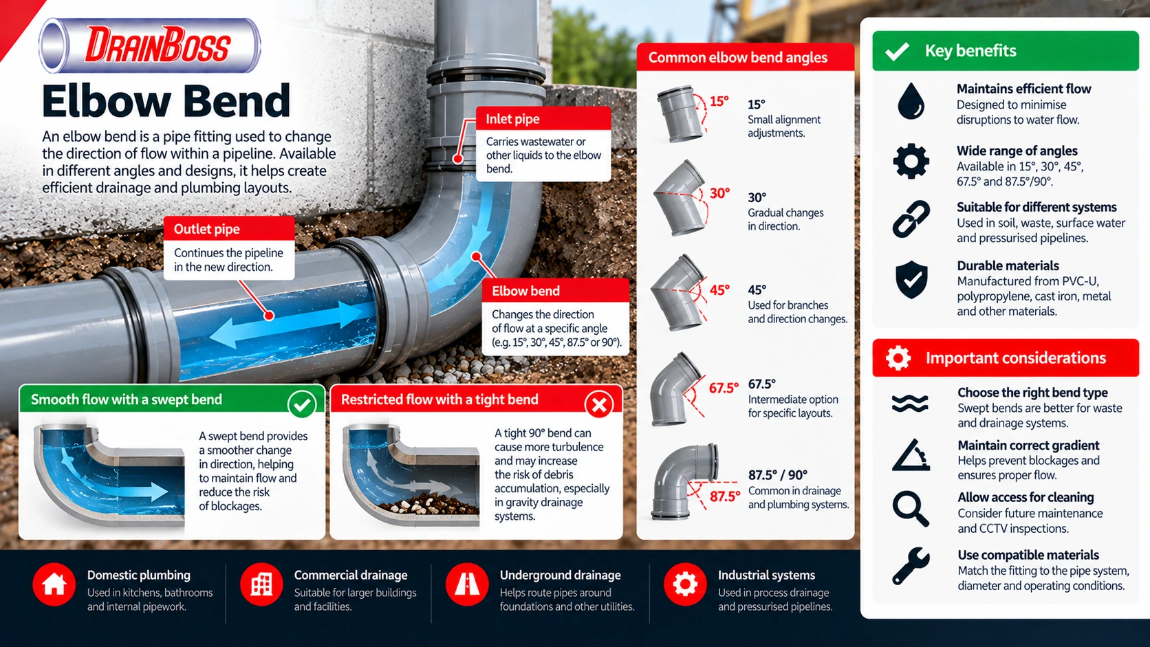
Elbow Bend Angles and Their Effect on Flow
The angle of an elbow bend describes the change in direction between the incoming and outgoing sections of pipe. A 45° bend changes the pipeline direction by 45°, while a 90° elbow produces a right-angle turn. The angle alone does not determine the fitting’s hydraulic performance, as the radius of curvature and internal geometry are also important.
In gravity drainage systems, wastewater moves through pipes primarily under the influence of gravity. The internal flow can contain suspended solids, toilet paper, grease and other material. A change in direction alters the flow pattern, and poorly designed bends may create areas where solids accumulate, particularly when the pipe has an insufficient gradient or operates with intermittent low flows.
A gradual bend generally allows flow to change direction more smoothly than a tight elbow of the same angle. However, the actual risk of blockage depends on the complete installation, including pipe diameter, gradient, discharge characteristics and the condition of the internal surface.
The following table compares common elbow bend configurations.
| Bend angle | Typical use | Main consideration |
|---|---|---|
| 15° | Minor alignment adjustments in drainage pipework | Allows small changes without significantly altering the route |
| 30° | Gradual changes in pipe alignment | Useful where a 45° fitting would create excessive deviation |
| 45° | Drainage branches and changes of direction | Commonly used where a less abrupt turn is desirable |
| 67.5° | Intermediate direction changes | Provides an alternative where standard 45° or 90° fittings do not suit the layout |
| 87.5° | Soil and drainage pipework, including certain branch and bend arrangements | Common in manufacturer-specific drainage systems |
| 90° | Right-angle connections in plumbing and drainage | Radius and fitting design must suit the intended flow |
Not every manufacturer supplies every angle in every diameter. Some drainage product ranges use 87.5° fittings rather than exactly 90°, while others offer both configurations. The nominal angle should therefore be checked against the actual fitting specification.
The difference between a tight elbow and a long-radius bend becomes particularly important when transporting wastewater containing solids. A tight change in direction may produce greater local turbulence and can make the passage of cleaning rods or CCTV equipment more difficult. A swept bend provides a larger radius, which can improve access and reduce abrupt changes in the flow path.
In pressurised pipework, bends create local hydraulic losses because the fluid changes direction. These losses depend on the fitting geometry, flow velocity, internal diameter and other factors. Engineers may account for them using a loss coefficient or an equivalent pipe length when calculating total system resistance.
For ordinary domestic plumbing, a single correctly specified elbow may have little practical effect on performance. However, numerous bends in a long pipe run can contribute to pressure losses, particularly where pipe diameters are small or flow velocities are high.
Elbow Bends in Soil, Waste and Underground Drainage
Elbow bends are used throughout domestic and commercial drainage systems, but their function varies according to the type of pipework. Soil pipes carry discharge from toilets and other sanitary appliances, while waste pipes typically serve sinks, baths, showers and similar fixtures. Underground drains convey wastewater or surface water towards a sewer, treatment system or another authorised discharge point.
In above-ground soil systems, bends are used to connect horizontal branches to vertical stacks, route pipes around structural elements and form changes in direction at the base of stacks. The arrangement must account for the movement of wastewater, entrained air and the possibility of pressure fluctuations within the system.
A vertical soil stack can carry discharge at relatively high velocities. At the base of the stack, the flow changes direction into a horizontal drain. A suitable swept bend or other approved arrangement helps accommodate this transition, while the overall design must consider hydraulic loading and ventilation.
For smaller waste pipes, elbows are frequently installed beneath kitchen sinks, behind appliances and within bathroom drainage connections. These installations often have limited space, making compact fittings attractive. However, unnecessary changes in direction can increase resistance and create additional locations where grease, soap residue or other deposits may accumulate.
Underground drainage introduces different considerations. Pipes must follow the designed gradient while accommodating changes in route around foundations, existing services and site boundaries. The use of bends should not create inaccessible sections that cannot be inspected or cleaned when problems develop.
Typical applications include:
-
Connecting horizontal waste pipes to vertical discharge arrangements.
-
Changing the direction of a soil pipe around structural obstacles.
-
Forming a suitable transition at the base of a soil stack.
-
Adjusting underground drainage alignments to avoid foundations or other utilities.
-
Connecting drainage branches where the fitting is appropriate for the direction of flow.
-
Routing surface water pipes towards gullies, inspection chambers or underground drainage networks.
-
Connecting pipework to pumping equipment, tanks or other drainage infrastructure.
The suitability of a bend depends on more than its angle. A fitting designed for above-ground waste pipework may not be suitable for burial, while a gravity drainage fitting may not have the pressure rating required for a pumped system.
Pipe diameter is another important factor. Domestic waste systems commonly use nominal pipe sizes around 32 mm, 40 mm and 50 mm, depending on the application and system specification. Soil pipework commonly uses a nominal size of 110 mm, while underground drainage networks may use larger diameters according to hydraulic requirements.
These sizes are not universal minimum requirements for every installation. The correct diameter must be selected according to the appliances served, expected discharge, pipe gradient and relevant design standards.
Bend Radius, Pipe Gradient and Blockage Risk
The radius of an elbow bend describes how gradually the pipe changes direction. A short-radius elbow produces a relatively tight turn, while a long-radius or swept bend follows a broader curve. Two fittings can have the same nominal angle but significantly different internal flow characteristics.
This distinction matters in gravity drainage because the flow is not normally under continuous pressure. Wastewater may travel as a partially filled stream, with air occupying the remaining space inside the pipe. Solids are transported by the moving water, and their behaviour depends on flow depth, velocity and the internal geometry of the drainage system.
Where a pipe changes direction abruptly, the flow pattern can become more complex. Local turbulence, changes in velocity distribution and interaction with the pipe wall may affect the transport of solids. A gradual bend can reduce the severity of the directional change, although it cannot compensate for inadequate gradient or poor pipe sizing.
Pipe gradient is particularly important. If a horizontal drain has insufficient fall, wastewater may move too slowly to transport solids effectively. If the gradient is excessive for the particular arrangement, water and solids may behave differently, and the overall hydraulic design still requires assessment.
An elbow bend should maintain the intended pipe alignment and gradient. Incorrect installation can create a local low point where water remains after discharge. This is sometimes described as a belly or sag in the pipe, and it can encourage sediment accumulation.
Several factors increase the likelihood of problems around bends:
-
Tight changes in direction combined with inadequate flow velocity.
-
Incorrectly installed fittings that create steps or internal misalignment.
-
Insufficient pipe gradient or localised sagging.
-
Grease, scale or sediment already reducing the internal diameter.
-
Multiple consecutive bends that restrict access for cleaning equipment.
-
Damaged or displaced joints that interrupt the internal flow path.
-
Inappropriate fitting dimensions or materials.
-
Root intrusion or structural defects near underground connections.
A blockage located at a bend does not necessarily mean that the bend angle is incorrect. Deposits may accumulate because of problems further upstream, while a restriction downstream can cause material to collect at the change in direction.
In kitchen drainage, fats, oils and grease are common contributors to recurring restrictions. Warm grease may enter the pipe in a relatively fluid state before cooling and adhering to internal surfaces. Bends and other locations where flow conditions change can become areas of accumulation, particularly when combined with low flow rates.
In underground drainage, silt and other sediment may collect where the pipe gradient is inadequate or the flow is insufficient to transport material. A bend can make an existing restriction more difficult to clear, but the underlying cause may be the drainage layout or operating conditions rather than the fitting itself.
For this reason, replacing a tight elbow with a swept bend may improve a particular installation without resolving every recurring blockage. The entire drainage run should be assessed where problems continue after cleaning.
Materials, Joint Types and Installation Requirements
Elbow bends are manufactured from a range of materials, including PVC-U, polypropylene, polyethylene, copper, stainless steel, cast iron and ductile iron. Material selection depends on the pipe system, operating temperature, pressure, chemical exposure and installation environment.
PVC-U fittings are widely used in domestic soil, waste and underground drainage. They are relatively lightweight, corrosion-resistant and available in numerous angles and diameters. Their suitability depends on the particular product specification, including whether the fitting is intended for above-ground or underground use.
Polypropylene is also common in waste and drainage applications. Certain polypropylene systems are designed for elevated discharge temperatures, although the allowable conditions depend on the manufacturer’s specifications. Polyethylene fittings may be used in welded pipe systems, including selected industrial drainage and pressure applications.
Metallic elbows are frequently used in water supply, heating, industrial pipework and specialist drainage systems. Copper elbows may be soldered, brazed or connected using approved mechanical methods. Steel and ductile iron fittings may use welded, flanged, grooved or mechanical joint arrangements according to the pipe system.
Common connection methods include solvent-weld joints, push-fit joints with elastomeric seals, compression fittings, threaded connections and welded joints. These methods are not interchangeable, and the fitting must be compatible with the pipe material and dimensions.
Solvent-weld joints are used in suitable thermoplastic systems. The process chemically joins compatible surfaces using an approved solvent cement, creating a permanent connection when correctly assembled and cured. Joint preparation, insertion depth and curing conditions must follow the manufacturer’s instructions.
Push-fit drainage fittings use elastomeric seals to provide watertight connections. These joints can allow limited movement where the system is designed for it, which may be useful in underground installations. Correct insertion depth, cleanliness and pipe alignment are essential to achieving a reliable seal.
When installing elbow bends, particular attention should be given to the following:
-
Confirm that the fitting is intended for the relevant pipe system, diameter and operating conditions.
-
Check the required angle and radius against the planned pipe route.
-
Inspect the fitting and sealing surfaces for damage or contamination.
-
Prepare the pipe ends according to the jointing method.
-
Maintain the required pipe gradient and avoid creating local low points.
-
Support the pipework appropriately so that the bend is not subjected to excessive mechanical stress.
-
Allow for thermal movement where required by the system design.
-
Inspect and test the completed installation using the appropriate procedure.
Underground bends require suitable bedding and surrounding support. Poorly compacted backfill or uneven loading can contribute to settlement and joint movement. The installation should also avoid direct contact with sharp objects that could damage plastic fittings or protective coatings.
Above-ground bends must be supported according to the pipe manufacturer’s requirements. A fitting should not be expected to carry the weight of an unsupported pipe run, particularly where the system experiences thermal expansion or repeated discharge loads.
Access for Drain Cleaning and CCTV Inspection
Changes in direction affect how drainage maintenance equipment moves through a pipe. Cleaning rods, mechanical cables, jetting hoses and CCTV cameras must pass around bends without becoming trapped or placing excessive force on the pipework.
A long-radius bend generally provides a more gradual route for this equipment than a tight elbow. However, the ability to negotiate a bend depends on the pipe diameter, equipment dimensions, stiffness of the cleaning cable or hose and the condition of the drainage system.
A CCTV camera designed for a 110 mm drainage pipe may be able to pass through certain bends that would restrict larger equipment. Similarly, flexible jetting hoses can navigate many changes in direction, but sharp or repeated bends can limit their movement.
Access points should therefore be considered during drainage design. Inspection chambers, rodding eyes and other suitable access arrangements allow engineers to investigate and clear blockages without dismantling extensive sections of pipework.
In underground drainage, changes of direction may require appropriate access arrangements under the applicable design and building requirements. Approved Document H in England addresses access to drainage systems and the need for drains to be accessible for clearing blockages.
The location of access points should reflect the drainage layout. A long underground run containing several bends but no suitable inspection access may be difficult to maintain, even if the pipe operates satisfactorily under normal conditions.
For existing drainage systems, recurring blockages around a bend may justify a CCTV survey. This can establish whether the problem involves accumulated material, displaced joints, damaged fittings, incorrect alignment or another defect.
CCTV inspection is particularly useful where the bend is buried beneath a driveway, patio or building. Identifying the actual cause can help avoid unnecessary excavation or replacement of pipe sections that remain structurally sound.
Drain jetting may be used to remove grease, sludge, sediment and certain other deposits from suitable pipework. The operating pressure and nozzle must be selected according to the pipe material, diameter and condition. High-pressure cleaning should not be used indiscriminately where a fitting is fractured, displaced or otherwise structurally vulnerable.
Mechanical cleaning equipment can also be appropriate for some restrictions. However, excessive force around a tight bend may damage the pipe or joint. If equipment repeatedly encounters resistance at the same location, further investigation is preferable to forcing it through.
Elbow Bends in Pressurised Pipework
Although elbow bends are common in gravity drainage, they are also important in pressurised water and wastewater systems. These include water supply pipelines, pumped drainage arrangements and sewer rising mains.
In a pressurised system, fluid is driven through the pipe by a pump or another pressure source. Every change in direction contributes some resistance to flow, and the total pressure loss must be considered when sizing pumps and pipelines.
The hydraulic effect of an elbow depends on the bend angle, radius, pipe diameter, flow velocity and internal surface condition. A long-radius bend may produce a lower local pressure loss than a short-radius elbow under comparable conditions, although actual performance depends on the fitting design.
Pressure loss becomes more important where a system contains numerous fittings. A short pipeline with several tight elbows may have a greater hydraulic resistance than its straight length alone would suggest. Designers therefore account for fittings when calculating the total head required from a pump.
Pressurised bends must also withstand forces generated by internal pressure. At a change in direction, pressure creates an unbalanced force that can act on the fitting and connected pipework. Depending on the pipe material and joint system, this may require restrained joints, thrust blocks or other engineered restraint arrangements.
These forces can be significant in larger pipelines. A fitting that is adequately rated for internal pressure may still require external restraint to prevent movement at the joint.
Pressure transients are another consideration. Sudden valve closure, pump stopping or other rapid changes in flow can generate pressure surges. The pipework and fittings must be suitable for the expected operating and transient conditions.
For sewer rising mains, elbow bends must also be compatible with wastewater and any relevant corrosion protection requirements. The fitting material, internal lining and joint system should be specified as part of the complete pipeline rather than selected independently.
Selecting the Correct Elbow Bend
The most suitable elbow bend is determined by the function of the pipeline and the constraints of the installation. A compact 90° elbow may be appropriate in certain pressurised plumbing arrangements, while a swept bend may be preferable in a gravity drainage run carrying solids.
The first consideration is the intended change in direction. The fitting must connect the pipe sections without forcing them out of alignment or introducing unnecessary stress. Where the required angle cannot be achieved using a standard fitting, an alternative combination may be necessary, provided it complies with the applicable system requirements.
The second consideration is the flow. Wastewater containing solids requires particular attention to bend geometry, gradient and access for cleaning. Pressurised water systems require consideration of local pressure losses and mechanical forces.
Available space also influences the choice. Long-radius bends occupy more room than compact elbows, which can create difficulties within narrow service voids or near structural elements. However, reducing the bend radius simply to fit the available space may compromise the intended drainage arrangement.
Material compatibility is equally important. A fitting must match the pipe’s dimensions, jointing method, operating temperature and pressure rating. Using components from different product systems without confirmed compatibility can create unreliable connections.
For underground installations, access and future maintenance should be considered before the pipe is buried. The location of bends, inspection chambers and other access points can have a substantial effect on the cost and difficulty of clearing future blockages.
Where an existing elbow repeatedly becomes obstructed, the cause should be established before selecting a replacement. A poorly aligned joint, insufficient gradient or downstream restriction may remain problematic even after the fitting has been changed.
An elbow bend is a relatively small component, but its geometry and installation can influence the performance of an entire drainage run. Correct angle selection, suitable bend radius, compatible materials and adequate maintenance access help ensure that the change in direction does not become a recurring point of restriction or failure.