What is a Expansion Coupling
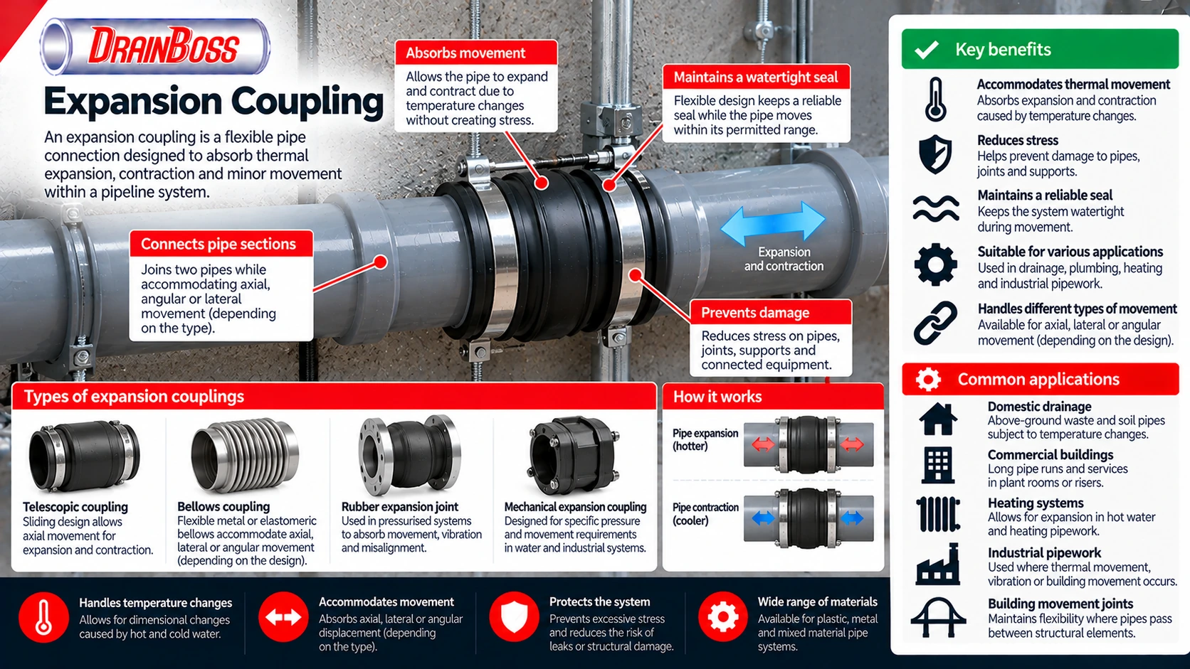
An expansion coupling is a pipe fitting designed to accommodate controlled movement within a pipeline caused by temperature changes, structural displacement or other operating conditions. Unlike a rigid connection, which holds adjoining pipe sections in a fixed position, an expansion coupling allows a specified amount of movement while maintaining a sealed connection. Depending on its design, the fitting may accommodate axial expansion and contraction, lateral displacement or angular movement. Its primary purpose is to prevent excessive mechanical stress from developing in pipes, joints, supports and connected equipment.
Expansion couplings are used in plumbing, drainage, heating, water distribution and industrial pipework. They are particularly important in long pipe runs, systems carrying water at changing temperatures and installations where pipes pass between structural elements that may move independently. Plastic drainage pipes often require careful consideration of thermal movement because thermoplastic materials generally expand and contract more than steel, copper or cast iron under comparable temperature changes.
The term expansion coupling covers several different types of fitting, including telescopic sliding joints, rubber expansion joints, metal bellows and specialist mechanical connections. These products have different movement capacities, pressure ratings and installation requirements. Selecting the correct fitting involves calculating the expected movement and ensuring that the surrounding pipework is properly supported and restrained.
Why Thermal Expansion Matters in Plumbing and Drainage
Most pipe materials change length when their temperature changes. As a pipe becomes warmer, it generally expands, while cooling causes contraction. The amount of movement depends on the material, pipe length and temperature difference. Although the dimensional change may be relatively small over a short section, it can become significant across a long continuous pipeline.
In domestic plumbing, temperature changes occur when hot water passes through previously cold pipes. Waste pipes connected to washing machines, dishwashers, baths and other appliances may experience repeated heating and cooling during normal operation. Above-ground drainage systems can also be affected by changes in ambient temperature, particularly in roof spaces, plant rooms, service risers and exposed external locations.
The approximate change in pipe length can be calculated using the following formula:
Change in length (mm) = Expansion coefficient (mm/m/°C) x Pipe length (m) x Temperature change (°C)
For example, consider a 6 m plastic pipe with an assumed thermal expansion coefficient of 0.07 mm/m/°C. If the pipe temperature increases by 40°C, the calculated expansion is 16.8 mm. This is a substantial movement for a pipe installed between rigid connections, particularly where the system includes branches, fixed supports or penetrations through building structures.
The coefficient used in this example is illustrative. Actual values depend on the pipe material and product specification, so manufacturer data should be used when designing a particular installation. The calculation also assumes that the temperature change is reasonably uniform along the pipe, whereas real drainage systems may experience different temperatures at different locations.
The following table shows approximate linear thermal expansion coefficients for common pipe materials.
| Pipe material | Approximate expansion coefficient, mm/m/°C | General characteristics |
|---|---|---|
| PVC-U | 0.06 to 0.08 | Relatively high thermal movement |
| Polypropylene (PP) | 0.10 to 0.15 | High thermal movement |
| Polyethylene (PE) | 0.15 to 0.20 | High thermal movement |
| Copper | 0.016 to 0.017 | Lower expansion than common thermoplastics |
| Carbon steel | 0.011 to 0.013 | Relatively low thermal movement |
| Ductile iron | Approximately 0.012 | Relatively low thermal movement |
These figures are indicative engineering values rather than guaranteed characteristics of every product. Pipe formulations, operating temperatures and manufacturing specifications can influence the coefficient used in design calculations. Some multilayer and reinforced pipes also behave differently from pipes manufactured entirely from a single thermoplastic material.
Thermal expansion is not inherently harmful. Problems develop when the pipe cannot move as intended or when its movement is transferred to components that are not designed to accommodate it. A pipe restrained at both ends may develop thermal stress, while an inadequately supported pipe may bow, sag or place additional loads on its joints.
An expansion coupling provides one method of controlling this movement. However, the fitting must operate together with suitable pipe supports, guides and fixed points. Installing an expansion coupling into an incorrectly supported pipeline does not automatically eliminate the stresses associated with temperature changes.
Types of Expansion Couplings and How They Work
Expansion couplings use different mechanical arrangements to accommodate pipe movement. The appropriate type depends on whether the pipeline must expand along its centreline, move sideways, change angle or accommodate a combination of these movements. The fitting must also remain suitable for the pressure, temperature and substances carried through the system.
A telescopic expansion coupling uses sliding components that move relative to each other. One section extends into another, allowing the connected pipe to expand or contract within a specified travel range. Elastomeric seals maintain the connection while the components move, provided that the fitting remains within its permitted operating conditions.
Telescopic fittings are used in selected plastic drainage and other pipe systems. Their movement allowance depends on the length of the sliding section, sealing arrangement and manufacturer specification. They are primarily intended for controlled axial movement and should not automatically be used to accommodate substantial lateral displacement.
Rubber expansion joints use the flexibility of an elastomeric element to accommodate movement. Depending on their construction, they may permit axial compression, extension, lateral displacement or angular movement. Some are also used to reduce the transmission of vibration between equipment and connected pipework, although their effectiveness depends on the complete installation.
Metal bellows expansion joints incorporate a corrugated metallic element that deforms under controlled movement. These fittings are used in selected heating, industrial and process piping systems where operating conditions require a suitable metallic pressure boundary. Their design may allow axial, lateral or angular movement, but individual products are normally engineered for specified movement modes and limits.
Mechanical expansion couplings may incorporate sliding sleeves, sealing glands or other components designed for controlled displacement. They can be used in selected water distribution and industrial pipelines where the connection must withstand particular pressure and movement conditions. Some designs require additional restraint or anchorage to manage forces generated by internal pressure.
The principal configurations include:
-
Telescopic expansion couplings. Sliding joints designed primarily to accommodate axial expansion and contraction.
-
Rubber expansion joints. Flexible elastomeric connections that can accommodate specified movement and, in some applications, vibration.
-
Metal bellows expansion joints. Corrugated metallic fittings used where the operating conditions and movement requirements justify their use.
-
Mechanical expansion joints. Specialist connections designed for particular pipe materials, pressures and movement allowances.
-
Building movement joint assemblies. Pipework arrangements designed to accommodate displacement between structural elements.
The direction of movement is important when comparing these products. Axial movement occurs along the pipe’s centreline, lateral movement occurs perpendicular to it, and angular movement changes the orientation of the connected pipe sections. A fitting designed for one movement type may have a much smaller allowance for another.
Ordinary flexible pipe couplings should not automatically be treated as expansion couplings. A flexible drainage connector may tolerate limited angular misalignment without providing sufficient axial travel for repeated thermal movement. Similarly, a rubber connector may allow minor displacement without being designed for continuous expansion and contraction cycles.
The manufacturer’s declared movement capacity should therefore be checked before installation. It is also important to establish whether different movement allowances can be used simultaneously, since a fitting operating near its maximum axial displacement may have a reduced permissible lateral or angular movement.
Expansion Couplings in Soil, Waste and Water Pipework
Above-ground soil and waste systems are common applications for thermal expansion allowances. Plastic drainage pipes may experience repeated temperature changes from wastewater discharge, while their routes often include long horizontal sections, vertical stacks and connections through building structures. The movement of these pipes must be managed without compromising joint integrity or the gradients required for gravity drainage.
In many proprietary plastic soil systems, thermal movement is accommodated through correctly installed socket joints and specified pipe support arrangements. Some systems incorporate expansion allowances within their standard connections, while others may require separate expansion fittings in particular circumstances. The correct method depends on the pipe material, jointing system, installation length and manufacturer instructions.
Vertical soil stacks require particular attention because thermal movement occurs alongside the weight of the pipework and the loads imposed by connected branches. A suitable support arrangement must carry the stack’s weight while allowing movement at designated locations. If the pipe is restrained incorrectly, expansion may transfer stress to branch connections, sockets or structural penetrations.
Horizontal waste pipes have different constraints. They must maintain a suitable gradient to transport wastewater while allowing for temperature-related movement. An expansion fitting that permits excessive sagging or misalignment may interfere with drainage performance even if the connection remains watertight.
For example, a long waste pipe connected to commercial kitchen equipment may experience repeated temperature changes as hot wastewater enters the system. The resulting movement depends on the pipe material, length and temperature variation. The installation must accommodate this movement without allowing the pipe to lose its intended alignment or impose excessive loads on connected fittings.
Expansion allowances may need particular consideration in the following situations:
-
Long horizontal waste pipe runs carrying intermittent hot discharge.
-
Vertical plastic soil stacks extending through several storeys.
-
Pipework exposed to substantial changes in ambient temperature.
-
Connections between materials with different thermal expansion characteristics.
-
Pipes passing between structural elements that may move independently.
-
Installations where rigid restraints could transfer movement into branches or equipment connections.
Not every installation in these categories requires a separate proprietary expansion coupling. Some systems accommodate the necessary movement through standard sockets, correctly positioned supports or other manufacturer-approved arrangements. Adding an unnecessary coupling can introduce another potential leakage point without improving the overall installation.
Pressurised water systems introduce additional requirements. An expansion coupling must withstand the operating pressure and any relevant pressure transients while accommodating the specified movement. The fitting may also experience axial forces generated by internal pressure, which must be managed through suitable anchors, restraints or specially designed joint arrangements.
Heating systems can require similar consideration, particularly where long pipe runs experience substantial changes between installation and operating temperatures. However, the selection of expansion joints for heating pipework depends on the pipe material, temperature range, pressure, support arrangement and applicable system design requirements.
Fixed Points, Sliding Supports and Building Movement Joints
An expansion coupling works correctly only when the surrounding pipework allows movement to reach the fitting in the intended direction. This requires a suitable arrangement of fixed points, sliding supports and guides. Without these components, the pipe may move unpredictably or transfer excessive forces to the coupling.
A fixed point is a support or anchor designed to restrain pipe movement at a selected location. It establishes a reference position from which thermal expansion or contraction can occur. A sliding support, by contrast, maintains the pipe’s alignment while allowing longitudinal movement.
In a simple straight pipe run, the expected thermal movement can be calculated from the pipe length and temperature change. The expansion coupling can then be positioned to accommodate the movement allocated to that section. However, real pipework often contains bends, branches, equipment connections and changes in support stiffness that affect the movement pattern.
A rigid connection to a branch may create an unintended restraint. Similarly, a pipe passing tightly through a wall or floor may be prevented from moving even if sliding supports are installed elsewhere. These conditions can cause thermal stress to develop in parts of the system that were not intended to carry it.
Sliding supports must also provide adequate vertical support. This is particularly important in gravity drainage, where excessive deflection can alter the pipe gradient and create locations where wastewater or sediment accumulates. The ability to move longitudinally should not come at the expense of maintaining the intended drainage alignment.
Building movement joints create another challenge. These joints are designed to accommodate relative movement between structural elements, which may result from thermal effects, settlement, structural deflection or other design conditions. Pipework crossing the joint can experience displacement that differs from ordinary thermal expansion within the pipe itself.
The expected structural movement may include longitudinal, lateral, vertical or angular displacement. A standard telescopic coupling may be suitable for controlled axial movement but inappropriate where the principal displacement occurs sideways. In such cases, a specially designed flexible connection or movement assembly may be necessary.
The required movement allowance must be established from the structural design rather than estimated from the width of the visible building joint. A fitting that accommodates compression but has insufficient extension capacity may fail when the structural elements move apart. The pipe supports on either side must also allow the intended movement without imposing excessive forces on nearby connections.
For drainage systems, the movement assembly must preserve a suitable internal flow path. Excessive sagging, deformation or internal misalignment can interfere with wastewater transport even when the fitting remains sealed. Where the pipe carries foul wastewater, leakage can also affect concealed building spaces and structural elements.
Installation Position, Movement Allowance and Pressure Forces
Expansion couplings are generally installed with a specified initial position so that sufficient movement remains available during operation. A telescopic fitting installed at the end of its permitted travel may have little capacity to accommodate further expansion or contraction. The correct starting position depends on the installation temperature and the expected operating temperature range.
Consider a pipe installed in relatively cold conditions that will later carry hot water. As its temperature rises, the pipe expands, and the expansion coupling must have sufficient travel in the required direction. If the pipe is installed close to its maximum operating temperature, a greater allowance may be needed for contraction as it cools.
Manufacturers may provide insertion marks, installation dimensions or specific setting procedures to establish the correct movement allowance. These instructions should be followed rather than estimating the insertion depth visually. The pipe should also be aligned correctly so that the fitting does not experience unnecessary bending or uneven seal loading.
Pipe ends must be prepared according to the fitting specification. Burrs, sharp edges and contamination can damage elastomeric seals during assembly. Where lubrication is required, it must be compatible with the seal material and approved for the intended application.
Sliding components should not be bonded together unless the manufacturer specifically requires it. Applying solvent cement to a surface intended to move would prevent the coupling from performing its expansion function. Mechanical and flanged expansion joints also require correct installation dimensions and fastening procedures to maintain reliable sealing.
Pressurised expansion joints require additional attention because internal pressure can generate forces that tend to extend the fitting. These forces are commonly described as pressure thrust. Their magnitude depends on the effective pressure area and the internal pressure acting on the joint.
For a simplified illustration, a pressure of 5 bar acting across an effective area of 0.01 square metres produces a force of approximately 5,000 newtons. The actual effective area depends on the joint design, so this calculation should not be used as a substitute for manufacturer data. Nevertheless, it demonstrates why a flexible connection can require substantial restraint even when its pressure rating is adequate.
Some expansion joint designs incorporate features intended to manage or balance pressure thrust. Others rely on external anchors, tie rods or engineered pipe restraint systems. The appropriate arrangement must be established during design, particularly where the fitting connects to pumps, valves or other equipment.
An expansion coupling should not be used to compensate for major installation errors. Incorrect pipe alignment, inadequate support or incompatible dimensions should be corrected rather than forced into a flexible connection. The fitting is intended to accommodate specified operating movement, not to replace proper pipework design.
Common Expansion Coupling Defects and Their Causes
Expansion couplings remain subject to wear, mechanical loading and material deterioration throughout their service life. Their durability depends on the operating temperature, pressure, movement range, number of movement cycles and the substances carried through the pipeline. A fitting that performs reliably in ordinary domestic drainage may not be suitable for a chemically aggressive or high-temperature industrial environment.
Elastomeric seals can deteriorate because of ageing, excessive temperature, chemical exposure or mechanical damage. Loss of sealing performance may lead to leakage during movement or pressure fluctuations. Sliding components can also become restricted by deposits, corrosion or deformation, preventing the fitting from accommodating the movement for which it was installed.
Incorrect support arrangements are another potential cause of failure. A coupling may be forced to carry pipe weight, accommodate excessive angular displacement or resist pressure forces that should have been transferred to suitable anchors. These conditions can overload seals, bellows or mechanical components even when the fitting itself is correctly manufactured.
Common problems include leakage around sealing elements, movement beyond the permitted travel, damaged bellows, excessive misalignment and restricted sliding action. The underlying cause should be established before a replacement fitting is installed. Otherwise, the same operating conditions may damage the new component.
For example, a telescopic coupling that repeatedly pulls apart may indicate excessive thermal movement, incorrect initial positioning or inadequate pipe restraint. Replacing the fitting with an identical component will not necessarily solve the problem if the surrounding installation remains unchanged.
Similarly, a leaking rubber expansion joint may be experiencing excessive lateral displacement or pressure thrust. Tightening its connections without checking the movement conditions may temporarily reduce leakage while increasing mechanical stress elsewhere in the system.
In accessible plant rooms and service areas, visual inspection can identify unusual deformation, leakage, corrosion or displacement. The frequency and scope of inspection should reflect the operating conditions and the consequences of failure. Concealed expansion joints are more difficult to maintain, so accessibility and future replacement should be considered during the original design.
Selecting an Expansion Coupling for Long-Term Performance
The correct expansion coupling must be selected according to the movement it is expected to accommodate and the conditions under which it will operate. Pipe diameter and material are essential, but they do not provide enough information to determine whether a fitting is suitable. Movement direction, operating temperature, pressure and support arrangements must also be considered.
The expected axial, lateral and angular movements should be established separately. Manufacturers may specify different limits for each movement type, and the maximum allowances may not be available simultaneously. A fitting selected solely because it offers sufficient axial travel may still be unsuitable if the installation also requires significant lateral displacement.
Temperature affects both the amount of thermal movement and the suitability of the coupling materials. The fitting must remain functional throughout the expected operating range, including periods of low temperature and intermittent hot discharge. Where movement occurs repeatedly, fatigue resistance and the expected number of operating cycles may also influence the selection.
For pressurised systems, the pressure rating must cover the relevant operating and testing conditions. Pressure thrust, transient pressures and the forces transferred to anchors or connected equipment must also be assessed. For drainage systems, maintaining the required pipe gradient and internal alignment is particularly important.
Chemical compatibility should be checked where the pipeline carries industrial wastewater, cleaning chemicals or other substances that may affect seals and flexible components. The installation environment also matters, especially where fittings are exposed to sunlight, moisture, corrosive conditions or mechanical damage.
The available space and future maintenance requirements should be considered before the fitting is installed. Some expansion joints require a greater installation length than ordinary couplings, while others need specific guide distances or anchoring arrangements. Where a fitting is likely to require inspection or replacement, it should remain accessible wherever practicable.
An expansion coupling should be treated as one component within a complete pipe movement control system. Its ability to prevent damage depends on the correct calculation of expected displacement, appropriate movement capacity, suitable pipe supports and installation in accordance with the manufacturer’s requirements. When these conditions are satisfied, the coupling allows the pipeline to respond to temperature changes and structural movement without transferring excessive stress to adjoining pipes and connections.