
What is a Filtration Trench
A filtration trench is a shallow, elongated drainage structure filled with permeable aggregate that collects surface water runoff and allows it to infiltrate gradually into the surrounding ground. It is used in sustainable drainage systems (SuDS) to manage rainfall close to where it falls, reducing the volume of water discharged directly into conventional surface water sewers. Depending on the design, a filtration trench may receive runoff from roofs, driveways, car parks, access roads and other impermeable surfaces.
The trench provides temporary storage within the spaces between aggregate particles while water moves into the underlying soil. Unlike a conventional drainage pipe, which primarily transports water away from a site, an infiltration-based trench is intended to retain runoff temporarily and release it through the base and, where appropriate, the sides of the excavation. Its performance therefore depends heavily on soil permeability, groundwater conditions, available storage volume and the quality of incoming runoff.
The terminology requires some care. In UK drainage engineering, an aggregate-filled trench designed primarily to discharge water into the ground is more commonly described as an infiltration trench. The term filtration trench may also be used for arrangements that filter runoff through granular media before conveying it elsewhere. Filtration and infiltration are related but different processes: filtration removes suspended material as water passes through a medium, while infiltration describes water entering the surrounding soil.
A filtration trench may perform both functions, but it should not be assumed that every aggregate-filled trench provides effective water treatment or that every filtration system allows water to infiltrate into the ground. The intended hydraulic function must be established before selecting the construction details.
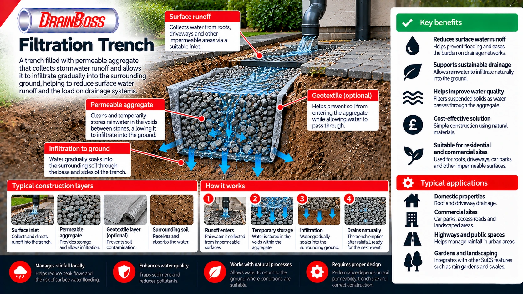
How a Filtration Trench Stores and Disperses Stormwater
The operating principle of a filtration trench is based on temporary storage and controlled infiltration. Rainfall runoff enters the trench through a suitable inlet arrangement, occupies the void spaces within the aggregate and gradually moves into the surrounding soil. As water infiltrates, storage capacity becomes available for subsequent rainfall.
The aggregate itself does not absorb most of the stored water. Storage is provided primarily by the interconnected spaces between stones, commonly referred to as the void volume. Clean, uniformly graded coarse aggregate can provide substantial void space, although the actual proportion depends on grading, particle shape and compaction.
A typical aggregate-filled trench may have a void ratio of approximately 30% to 40%, but the design value should be based on the specified material. This means that a trench containing 10 cubic metres of aggregate does not provide 10 cubic metres of usable water storage.
For example, a trench measuring 10 m long, 1 m wide and 1 m deep has a gross volume of 10 cubic metres. If the aggregate provides 35% effective void space, the theoretical storage volume is approximately 3.5 cubic metres. This calculation assumes the entire aggregate volume is available for storage and does not account for sediment accumulation, residual water or other site-specific limitations.
The basic storage relationship is:
Storage volume (m3) = Trench length (m) x Trench width (m) x Aggregate depth (m) x Effective void ratio
This calculation is useful for estimating the storage provided by the aggregate, but it does not establish whether the trench can manage the runoff from a particular rainfall event. The rate at which water enters and leaves the structure must also be considered.
During rainfall, runoff may enter faster than it can infiltrate into the ground. Water therefore accumulates temporarily within the aggregate. After rainfall decreases or stops, the stored water continues to infiltrate until the trench drains down.
The rate of infiltration depends on the surrounding soil and the available infiltration area. Sandy and gravelly soils may allow relatively rapid movement of water, while soils containing substantial clay fractions may have much lower permeability.
The relationship is not determined by soil classification alone. Compaction, soil structure, groundwater conditions and the presence of less permeable layers can substantially affect infiltration performance.
Where the underlying ground has insufficient infiltration capacity, water may remain within the trench for extended periods. This reduces the storage available for subsequent storms and can eventually cause the system to overflow.
Filtration Trench Construction and the Function of Each Layer
A filtration trench generally consists of an excavated channel containing permeable aggregate, with an inlet arrangement and suitable protection against sediment entering the storage layer. The precise construction varies according to the runoff source, ground conditions and the intended drainage performance.
Some trenches receive water through a surface gravel strip, while others use a perforated distribution pipe to introduce runoff along the trench. The distribution arrangement can influence how evenly water enters the aggregate and whether flow becomes concentrated in one location.
A geotextile may be installed between the aggregate and surrounding soil to provide separation and reduce migration of fine particles. However, geotextile selection requires care because unsuitable fabric can become clogged or restrict infiltration. The need for a geotextile, its permeability and its position should be determined by the design rather than assumed to be identical for every installation.
Typical construction components include:
-
Surface inlet or distribution arrangement. Directs runoff into the trench without causing concentrated erosion or unnecessary sediment accumulation.
-
Permeable aggregate. Provides interconnected voids for temporary water storage and allows water to move through the structure.
-
Perforated distribution pipe. May be included to spread incoming runoff along the trench, depending on the design.
-
Geotextile separation layer. Can help prevent migration of surrounding soil into the aggregate where appropriately specified.
-
Inspection or observation point. Allows water levels and drain-down performance to be checked.
-
Overflow connection. Provides a controlled route for excess water where the design requires one.
-
Underlying and surrounding soil. Receives infiltrating water and ultimately determines whether the system can drain at the required rate.
The upper surface may be finished with gravel or another suitable permeable arrangement. Where runoff enters directly through the surface, the design must account for sediment, leaves and other debris that could obstruct the inlet.
A filtration trench should not automatically be filled with ordinary mixed construction aggregate. Material containing excessive fines can reduce the available void space and restrict water movement. The selected aggregate must be appropriate for drainage storage and compatible with the structural requirements of the installation.
The excavation base is also important. Smearing or compacting the soil during construction can reduce its infiltration capacity, particularly in cohesive soils. Construction methods should therefore avoid unnecessary disturbance of the infiltration surface.
Where the trench is installed close to traffic or other loading, the structural design must account for the loads imposed on the surrounding ground. A drainage trench intended for a landscaped area should not be assumed suitable beneath a heavily trafficked surface without appropriate engineering assessment.
Soil Permeability, Infiltration Testing and Groundwater Conditions
The suitability of a filtration trench depends primarily on whether the surrounding ground can accept water at an adequate rate. A trench can provide temporary storage, but it cannot operate as an effective infiltration system if the water has nowhere to go.
Site investigation should establish the relevant soil conditions, groundwater level, nearby structures and potential pathways for water movement. The presence of permeable material near the surface does not necessarily mean that the deeper ground will drain effectively.
For example, a site may contain a shallow layer of granular made ground above relatively impermeable clay. Water entering the trench may move through the upper layer but accumulate above the clay. This can cause prolonged saturation or lateral movement towards nearby structures.
Field infiltration testing is therefore preferable to relying solely on a general description of the soil. In the UK, infiltration testing for soakaways is commonly associated with the procedures described in BRE Digest 365. The suitability of a particular test method depends on the drainage design and the type of infiltration feature being proposed.
Tests should represent the proposed infiltration depth and relevant ground conditions. Results from a shallow trial pit may not accurately describe performance at a substantially different depth.
The following table shows how different site characteristics can affect filtration trench design.
| Site characteristic | Potential effect | Design implication |
|---|---|---|
| Highly permeable granular soil | Water may infiltrate relatively quickly | Storage and runoff treatment still require assessment |
| Low-permeability clay soil | Slow infiltration and prolonged water retention | A conventional infiltration trench may be unsuitable |
| High groundwater level | Reduced unsaturated depth and potential groundwater interaction | Groundwater separation and seasonal variation must be assessed |
| Compacted subsoil | Reduced infiltration capacity | Construction methods and measured infiltration rates are important |
| Layered ground | Water may accumulate above less permeable strata | Investigation must consider the full soil profile |
| Contaminated ground | Infiltration may mobilise pollutants | Infiltration may be restricted or require specialist assessment |
| Nearby foundations | Additional water may affect ground moisture conditions | Location and separation require site-specific assessment |
| Steeply sloping ground | Water may move laterally or emerge downslope | Ground stability and discharge pathways must be considered |
Groundwater separation is particularly important. Infiltration features should not be designed without considering the seasonal maximum groundwater level and the potential for water to reach sensitive receptors.
A trench that drains adequately during a dry summer may perform differently when groundwater levels rise during winter. The available infiltration gradient can decrease, and the structure may retain water for longer.
Contaminated land presents another constraint. Allowing runoff to infiltrate through contaminated soil may mobilise pollutants and create a pathway towards groundwater. In these circumstances, a lined drainage feature or another surface water management method may be more appropriate.
Infiltration can also be unsuitable where ground stability is a concern. Introducing additional water into certain slopes, made ground or areas near retaining structures may change pore water pressures and affect stability.
The design should therefore consider the consequences of infiltration beyond the trench itself. Managing surface runoff successfully at one location should not create groundwater or structural problems elsewhere.
Runoff Volume, Trench Dimensions and Drain-Down Time
A filtration trench must be sized according to the runoff it receives and the rate at which water can infiltrate into the surrounding ground. The contributing catchment area is a major factor because it determines how much rainfall can reach the structure.
For a simplified estimate, runoff volume can be calculated from rainfall depth, contributing area and an appropriate runoff coefficient.
Runoff volume (m3) = Rainfall depth (m) x Catchment area (m2) x Runoff coefficient
Consider a paved area of 150 square metres receiving 20 mm of rainfall. If an illustrative runoff coefficient of 0.9 is used, the estimated runoff volume is:
0.020 x 150 x 0.9 = 2.7 cubic metres
This calculation provides an approximate runoff volume for the assumed event. It does not account for the timing of rainfall, losses during the event, infiltration occurring simultaneously or the performance of upstream drainage components.
If the trench has an effective storage volume of 3.5 cubic metres, it may appear to have sufficient theoretical capacity for the calculated runoff volume. However, this does not prove that the design is adequate for the site.
A complete hydraulic assessment must consider rainfall duration, peak inflow, infiltration rate, available storage and the consequences of exceedance. UK drainage design also needs to consider the relevant design storm requirements and any applicable climate change allowances.
Drain-down time is another important parameter. A trench that takes too long to empty may still contain substantial water when the next rainfall event begins.
The time required for a trench to drain depends on the stored water volume, infiltration area and infiltration rate. In practice, infiltration behaviour may change as the water level falls and the wetted area decreases.
Design guidance for infiltration systems commonly requires assessment of how quickly stored water drains after a design event. The applicable criterion should be taken from the relevant drainage standard, approving authority requirements and project specification rather than applying a single universal drain-down time to every trench.
Trench geometry also affects performance. Increasing the depth provides additional storage, but it does not necessarily increase the effective infiltration area in the same proportion.
A longer or wider trench may provide more base area for infiltration, while a deeper trench may increase storage without providing a comparable increase in the area through which water can leave.
This distinction matters on sites with low infiltration rates. Simply excavating a deeper trench may not resolve inadequate drainage performance and can introduce additional groundwater or construction constraints.
Filtration Trenches, French Drains and Other SuDS Features
Filtration trenches are sometimes confused with French drains, soakaways and filter drains because these systems can all incorporate permeable aggregate. Their appearance may be similar, but their intended functions are not necessarily the same.
A French drain generally uses an aggregate-filled trench, often containing a perforated pipe, to collect and redirect water. It may be used to intercept groundwater or manage surface water, depending on its construction and location.
A filtration trench intended for infiltration uses the surrounding soil as the receiving medium. Its primary objective is to provide temporary storage and allow runoff to enter the ground.
A soakaway performs a similar infiltration function but is often constructed as a pit, chamber or modular storage system rather than a long narrow trench. The difference is mainly in geometry and construction, although individual designs may incorporate different treatment and distribution arrangements.
A filter drain, as used in some highway drainage applications, may collect water through a permeable aggregate layer and convey it along a perforated pipe towards an outlet. It should not automatically be assumed to dispose of all collected water by infiltration.
The distinction can be summarised through the following functional differences:
-
An infiltration trench is designed to store runoff temporarily and discharge it into suitable surrounding soil.
-
A French drain commonly intercepts water and may convey it to another drainage point.
-
A filter drain can provide filtration and collection, often with a perforated carrier pipe.
-
A soakaway provides underground storage and infiltration, commonly within a more compact footprint.
-
A lined filtration feature may treat or temporarily store runoff without allowing infiltration into the surrounding ground.
These definitions describe common arrangements rather than rigid product categories. A particular installation may combine collection, filtration, storage and infiltration within one structure.
The distinction is especially important when assessing an existing drainage problem. A perforated pipe surrounded by gravel does not prove that the system was intended to infiltrate water. It may instead have been designed to collect groundwater and transport it towards an outfall.
Identifying the intended outlet and hydraulic function is therefore essential before modifying or repairing the system.
Sediment Loading, Clogging and Water Quality
The long-term performance of a filtration trench depends on keeping its infiltration surfaces and aggregate voids sufficiently open. Stormwater runoff can carry sediment, organic matter, tyre particles, litter and other contaminants, particularly from roads and paved areas.
As suspended solids enter the trench, some particles may become trapped near the inlet, within the aggregate or at the boundary between the aggregate and surrounding soil. Over time, this can reduce the rate at which water moves through the structure.
Clogging is one of the main operational risks for aggregate-based infiltration systems. Once fine sediment has penetrated deeply into the aggregate, restoring the original permeability may be difficult without removing and replacing part of the material.
The risk depends on the characteristics of the contributing area. Roof runoff generally has a different pollutant and sediment profile from runoff collected from a busy car park or industrial yard.
Where runoff carries significant sediment, pretreatment may be necessary. This can involve a suitable silt trap, sedimentation chamber, vegetated filter strip or another arrangement designed to intercept material before it enters the trench.
The selected pretreatment method should match the expected contaminants and maintenance arrangements. A small silt trap may reduce coarse sediment entering the system but will not necessarily remove dissolved pollutants or fine suspended particles effectively.
Filtration through aggregate can remove some particulate material, but pollutant treatment performance varies. Clean coarse aggregate alone should not be assumed to provide the same treatment as an engineered filter medium or a properly designed bioretention system.
Dissolved substances may pass through the aggregate and enter the surrounding ground. This is particularly relevant where runoff contains hydrocarbons, metals, salts or other pollutants that could affect groundwater.
In the UK, SuDS design commonly considers pollution hazard and the treatment measures required for different runoff sources. The level of treatment should reflect the nature of the contributing surface and the sensitivity of the receiving environment.
Runoff from potentially contaminated industrial areas may be unsuitable for direct infiltration without additional controls. The drainage design should establish whether infiltration is acceptable before relying on an aggregate trench as the primary treatment measure.
Location, Overflow Provision and Construction Constraints
A filtration trench must be positioned where it can receive runoff without creating unacceptable risks to buildings, neighbouring land or underground infrastructure. Its location should be considered alongside the site drainage layout, ground conditions and maintenance access.
Infiltration features are commonly subject to separation requirements from buildings and other sensitive structures. In England, Approved Document H includes guidance relevant to soakaways and infiltration drainage, but the suitability of a particular trench must still be assessed against its design and site conditions.
A single separation distance should not be applied without considering the type of infiltration system and the applicable requirements. Ground permeability, foundation depth, groundwater conditions and the scale of the drainage feature may influence the assessment.
Nearby underground utilities can also affect the layout. Excavating around electricity cables, gas pipes, water mains or other services introduces construction risks, while prolonged saturation of the surrounding ground may be undesirable in certain circumstances.
Overflow provision is important because infiltration systems have finite storage and discharge capacity. During exceptional rainfall or when the ground is already saturated, inflow may exceed the rate at which water can infiltrate.
A controlled overflow can direct excess runoff towards a suitable drainage route or designated exceedance pathway. Without an appropriate arrangement, water may emerge at the surface and travel towards buildings, roads or neighbouring properties.
The consequences of exceedance should be considered during design rather than treated as an unexpected failure. Even a correctly sized infiltration trench may be exceeded during rainfall more severe than its design event.
Construction sequencing also affects performance. If the trench is installed early in a development and receives runoff from exposed soil or unfinished surfaces, large quantities of sediment may enter before the site is completed.
Protecting the infiltration area during construction can reduce this risk. The trench may need to remain isolated from sediment-laden runoff until the contributing surfaces have been stabilised and suitable pretreatment is operational.
Heavy construction traffic should not be allowed to compact the infiltration base unnecessarily. The excavation should also be protected from contamination by concrete washout, fuel, soil stockpiles and other construction materials.
Maintenance and Signs of Reduced Infiltration Performance
Filtration trenches require maintenance even though much of the system is buried. Their performance depends on the condition of the inlet, aggregate storage and infiltration surfaces, all of which can deteriorate if sediment and debris are allowed to accumulate.
Inspection is particularly important after substantial rainfall because the water level and drainage response can provide evidence of how the system is functioning. Observation points can make it easier to assess whether stored water is draining within the expected period.
Persistent standing water is one of the clearest signs that an infiltration system may not be performing as intended. However, the cause should be investigated rather than immediately assuming that the aggregate is blocked.
High groundwater levels, unusually intense rainfall, restricted inlets and changes in the surrounding soil can all affect drain-down performance. A trench may also appear to be functioning poorly because the contributing catchment has increased since the original installation.
Maintenance activities may include:
-
Removing leaves, litter and sediment from surface inlets.
-
Emptying upstream silt traps or sediment collection chambers.
-
Inspecting observation points and recording water levels.
-
Checking for persistent surface ponding after rainfall.
-
Investigating sediment accumulation near distribution pipes.
-
Maintaining vegetated pretreatment areas where provided.
-
Inspecting overflow connections for obstruction.
-
Replacing clogged aggregate or other components where necessary.
The required frequency depends on the runoff source, sediment loading, design and local conditions. A trench serving a relatively clean roof drainage area may have different maintenance needs from one receiving runoff from a heavily used access road.
Where performance has deteriorated, investigation should establish whether the restriction is located at the inlet, within the aggregate or at the soil interface. Cleaning an upstream pipe will not necessarily restore infiltration if the surrounding ground has become clogged.
Similarly, replacing the aggregate may provide limited improvement if the original problem was insufficient soil permeability. The underlying hydraulic conditions should be reassessed before undertaking substantial reconstruction.
A filtration trench can provide an effective method of managing surface water where the ground is suitable and the system is designed for the expected runoff. Its reliability depends on adequate infiltration capacity, correctly specified storage, sediment control and a safe route for excess water. These factors determine whether the trench continues to disperse rainfall into the ground or gradually becomes an underground storage feature that cannot empty at the required rate.