
What is a Flow Path
A flow path is the route followed by water as it moves through a drainage or sewerage system, from the point where it enters the network to its eventual discharge, treatment or infiltration point. In a typical drainage system, this route may include gullies, underground pipes, inspection chambers, manholes, junctions, pumping stations and outfalls. The flow path determines how water is conveyed through the network and influences drainage capacity, maintenance requirements and the consequences of blockages or structural defects.
In gravity drainage, water generally moves from higher to lower hydraulic levels, with pipe gradients and hydraulic conditions governing its movement. However, the route is not always a simple downward sequence. Water may pass through surcharged pipes, be lifted by pumps or encounter downstream restrictions that affect its level and velocity. The physical layout of the drainage network and the hydraulic conditions within it must therefore be considered together.
Understanding the flow path is essential when investigating blocked drains, tracing connections, designing new pipework or assessing surface water flooding. A drainage defect may produce symptoms some distance from its actual location, particularly where several branches connect to a common downstream pipe. Identifying the complete route allows engineers to establish which parts of the system are connected, where flow is restricted and how changes in one section may affect the wider network.
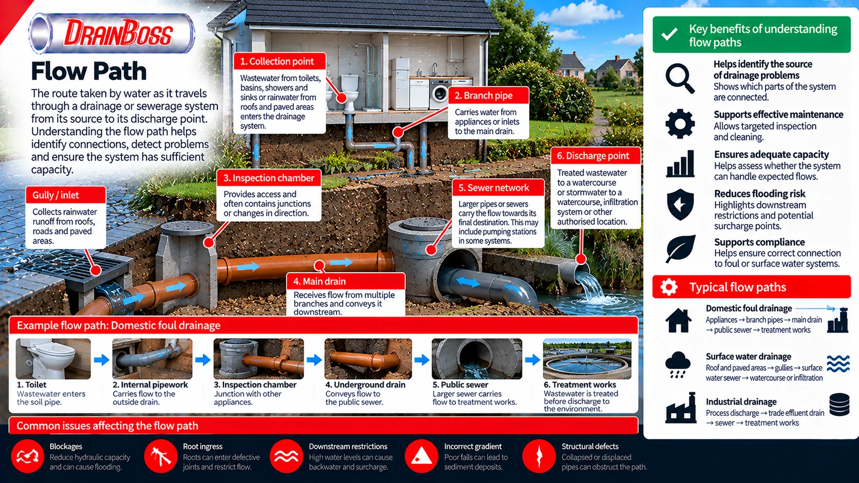
How Water Moves Through a Drainage Network
A drainage flow path begins at a collection point. In domestic foul drainage, this may be a toilet, basin, sink, shower or another appliance connected to the building’s soil and waste system. In surface water drainage, the starting point may be a roof gutter, rainwater downpipe, road gully, channel drain or other inlet receiving rainfall runoff.
The collected water then passes through a series of connected components. Each component has a particular function, but the complete route must provide sufficient hydraulic capacity to convey the expected discharge.
In a typical gravity-fed foul drainage system, wastewater moves from individual appliances into branch pipes before entering larger soil pipes or underground drains. Several branches may combine at junctions or inspection chambers, eventually discharging into a private drain, lateral drain or public sewer, depending on the property’s drainage arrangement.
The route taken by surface water may be different. Rainfall collected from roofs, paved areas and roads can be directed towards a surface water sewer, attenuation system, infiltration feature or suitable watercourse. The receiving arrangement depends on the drainage design, local infrastructure and applicable discharge requirements.
A typical drainage flow path may contain the following stages:
-
Collection point, where wastewater or rainfall runoff enters the drainage system.
-
Branch pipe or inlet connection, which carries water away from the collection point.
-
Main drainage run, which receives discharge from one or more upstream branches.
-
Inspection chamber or manhole, providing access and sometimes accommodating junctions or changes in direction.
-
Downstream conveyance system, such as a larger drain, sewer, culvert or pumped rising main.
-
Final receiving point, which may be a treatment works, infiltration system, watercourse or another authorised discharge location.
Not every drainage system contains all these components. A short private surface water system may discharge directly into a suitable soakaway, while a complex sewer network can include multiple pumping stations, storage structures and major trunk sewers.
The distinction between foul and surface water flow paths is particularly important. In a separate drainage system, wastewater and rainfall runoff are conveyed through different networks. In a combined sewer system, both may enter the same sewer, increasing the variation in flow during wet weather.
A connection that appears physically possible is not necessarily a permitted drainage route. The intended receiving system must be established before new connections are installed or existing pipework is altered.
Pipe Gradient, Velocity and Hydraulic Capacity
The movement of water through gravity drainage is influenced by the energy available to drive the flow. Pipe gradient is an important factor, but it is not the only one. Pipe diameter, roughness, flow depth, downstream water level and local hydraulic losses also affect the discharge that can pass through a drainage run.
In an ordinary gravity drain operating partially full, the water surface slopes in the direction of flow. The hydraulic conditions are influenced by the longitudinal gradient of the pipe and the resistance created by its internal surface.
A steeper gradient generally provides more driving energy for flow under otherwise comparable conditions. However, increasing the gradient does not automatically resolve every drainage problem, and excessively steep or poorly designed arrangements may introduce other operational considerations.
Drainage design must account for both hydraulic capacity and the movement of solids. Foul drainage pipes need suitable flow conditions to transport suspended and settleable material without allowing excessive deposition.
For example, a pipe with an insufficient gradient may carry water during high discharge but allow solids to settle during lower flows. Over time, these deposits can reduce the available cross-sectional area and contribute to recurring restrictions.
The relationship between flow rate, cross-sectional area and average velocity is:
Flow rate (m3/s) = Flow area (m2) x Average velocity (m/s)
For a circular pipe flowing full, the internal cross-sectional area can be calculated from its diameter. A pipe with an internal diameter of 150 mm has a cross-sectional area of approximately 0.0177 square metres.
If the average velocity is 1 m/s, the corresponding flow rate is approximately 0.0177 cubic metres per second, equivalent to 17.7 litres per second. This is a mathematical illustration rather than a statement of the actual capacity of a particular drainage pipe.
Real gravity drains frequently operate partially full, so the wetted flow area changes with water depth. The relationship between discharge and velocity must also account for friction, gradient and the hydraulic characteristics of the pipe.
The following table summarises the main factors affecting a drainage flow path.
| Hydraulic factor | Effect on water movement | Practical significance |
|---|---|---|
| Pipe gradient | Influences the energy available for gravity flow | Incorrect falls can contribute to poor drainage and deposition |
| Internal diameter | Determines the available cross-sectional area | Undersized pipes may lack capacity during peak discharge |
| Pipe roughness | Influences frictional resistance | Rough or deteriorated surfaces can increase hydraulic losses |
| Flow depth | Changes the wetted area and hydraulic conditions | Partially filled and surcharged pipes behave differently |
| Bends and junctions | Can introduce local hydraulic losses | Poorly configured connections may affect flow and maintenance |
| Sediment deposits | Reduce the effective flow area | Can contribute to recurring restrictions and blockages |
| Downstream water level | Can restrict discharge and cause backwater | May produce upstream surcharge without a local blockage |
| Pump operation | Adds energy to move water through the system | Flow depends on pump performance and system resistance |
These factors interact rather than operating independently. A drainage pipe may have an adequate diameter but perform poorly because of a downstream restriction. Similarly, a relatively steep pipe may still surcharge if its receiving sewer cannot accept the incoming flow.
Hydraulic capacity should therefore be assessed along the complete relevant flow path rather than at a single isolated pipe section.
Flow Paths at Junctions, Chambers and Changes in Direction
Drainage networks rarely consist of one uninterrupted straight pipe. They contain bends, branch connections, inspection chambers and changes in diameter or level. Each transition can influence how water moves through the system.
A junction combines flows from two or more upstream branches. The resulting hydraulic conditions depend on the angle of connection, relative discharges, pipe sizes and downstream capacity.
Where possible, drainage connections should be arranged to direct incoming water towards the intended downstream route. Poorly aligned connections may create turbulence, localised deposition or difficulties when cleaning and inspecting the pipework.
Inspection chambers and manholes are important because they provide access to the drainage network and may contain several connections. The channels formed within the chamber base help guide water from the incoming pipes towards the outlet.
A properly formed chamber channel should provide a continuous route for flow. Poorly constructed channels, damaged benching or accumulated debris can create local restrictions and areas where wastewater collects.
In some drainage networks, a chamber also marks a change in pipe diameter or level. These transitions require appropriate hydraulic design to avoid creating unnecessary losses or conditions that encourage sediment accumulation.
Changes in direction are not automatically problematic. Properly designed bends and junctions are normal components of drainage systems, and their suitability depends on the pipework arrangement and operating conditions.
However, the geometry can affect maintenance access. A sharp change in direction may make it more difficult to pass CCTV inspection equipment or drain-cleaning tools through a particular route.
A flow path may also divide at a hydraulic structure. Stormwater networks can incorporate flow controls, overflow arrangements or diversion structures that direct water towards different downstream routes under specified conditions.
For example, an attenuation system may release runoff through a controlled outlet while providing an emergency overflow for water exceeding the intended storage or discharge capacity. The normal flow path and the exceedance route must both be considered.
In combined sewer networks, certain structures can divert excess wet-weather flow towards a permitted overflow arrangement under defined operating conditions. These systems are subject to specific regulatory and operational requirements and should not be confused with ordinary drainage junctions.
The important distinction is between the physical connection and the actual hydraulic route. A pipe may be connected to a chamber but carry little or no flow under certain conditions, while another branch may become active only when water levels rise.
How Flow Paths Change During Heavy Rainfall and Surcharge
The route and behaviour of water can change when the drainage network approaches or exceeds its available capacity. During normal operation, a gravity sewer may flow partially full with a free water surface. During heavy rainfall or high wastewater discharge, the water level can rise until the pipe becomes completely filled.
This condition is known as surcharge. Once a pipe is surcharged, its hydraulic behaviour differs from ordinary partially full gravity flow because pressure and hydraulic head become important in determining the movement of water.
Surcharge does not necessarily mean that water is flowing in the wrong direction. It indicates that the hydraulic grade line has risen above the pipe crown at the relevant location. Whether water escapes from the system depends on the available levels, connections and surrounding structures.
If the hydraulic grade line rises sufficiently, wastewater or stormwater may back up through low-level connections, gullies or manholes. This can occur even when the local pipe is structurally sound and free from a physical blockage.
Downstream restrictions are particularly important. A high water level in a receiving sewer, river or storage system can reduce the ability of upstream drainage to discharge.
For example, a surface water outfall connected to a river may experience backwater when the river level rises. The drainage pipe can become surcharged because the downstream water level restricts its discharge, even though the pipe itself remains unobstructed.
Flow reversal is also possible under certain hydraulic conditions. If the pressure or water level at the downstream end becomes sufficiently high relative to the upstream end, water may move back through a connected section unless an appropriate arrangement prevents it.
Non-return valves are used in selected applications to reduce the risk of reverse flow. However, they must be correctly specified and maintained, and their presence can affect drainage operation when downstream conditions prevent normal discharge.
Heavy rainfall can also activate alternative surface flow paths. When gullies and pipes cannot accept all the incoming runoff, water may travel along roads, driveways and other low-lying routes.
These overland routes are part of the wider drainage behaviour of a site, even though they are not contained within underground pipes. Their direction depends on ground levels, kerbs, walls, entrances and other features affecting surface runoff.
For flood risk assessment, it is therefore important to consider both the designed underground flow path and the routes water may take when the system is exceeded.
Tracing a Flow Path During Drainage Investigations
Identifying the actual flow path is a common requirement during drainage surveys and investigations. The available drawings may be incomplete, particularly for older properties where extensions, repairs and changes in land use have altered the original pipework.
A drainage plan can indicate the intended route, but it does not always confirm the current arrangement. Connections may have been abandoned, diverted or installed differently from the recorded design.
CCTV drain surveys provide direct information about accessible pipe interiors. The camera can identify junctions, changes in direction, pipe materials and structural defects, helping engineers understand how different sections connect.
However, a CCTV camera does not automatically establish the destination of every branch. Some connections may be inaccessible, submerged or difficult to identify from one inspection direction.
A sonde fitted to suitable inspection equipment can assist with locating underground pipework from the surface. The signal can be detected using compatible locating equipment, helping establish the route and approximate depth of the inspected section.
Drain tracing may also involve controlled water testing or the use of suitable tracing dyes. These methods can help establish whether discharge from a particular inlet reaches a known downstream chamber or outlet.
The choice of method depends on the system and the information required. Dye testing must be planned to avoid inappropriate discharge, cross-contamination or misleading results caused by interconnected drainage routes.
Typical investigation objectives include:
-
Identifying which appliances or surface water inlets connect to a particular drain.
-
Establishing the route between inspection chambers.
-
Locating concealed junctions and changes in direction.
-
Confirming whether a pipe connects to a foul, surface water or combined sewer.
-
Finding the position of a suspected blockage or collapsed section.
-
Determining whether an abandoned pipe remains hydraulically connected.
-
Establishing the destination of an existing drainage discharge.
-
Recording the layout before construction, repair or redevelopment.
Flow direction can sometimes be inferred from pipe levels and chamber arrangements, but assumptions should be checked where the result matters. An incorrectly identified outlet can lead to unsuitable repairs or connections.
A drainage survey may also reveal that the observed flow path differs from the intended design. For example, an undocumented connection could allow roof runoff to enter a foul sewer, or wastewater could be connected to a surface water drainage system.
Such arrangements require careful assessment because they may create operational problems or involve drainage misconnections that need correction.
The resulting survey information can be recorded on a drainage plan showing pipe routes, directions of flow, chamber locations, pipe diameters and relevant levels. Accurate records make subsequent maintenance and investigation more efficient.
Flow Path Restrictions and Their Effects on Drainage Performance
A blockage affects the flow path by reducing or preventing water movement through part of the network. The symptoms depend on where the restriction occurs relative to the connected inlets and the available storage within the upstream pipework.
A blockage in a small branch serving one appliance may produce a local drainage problem. A restriction in a shared downstream drain can affect several fixtures or properties connected to the same section.
This distinction is important when interpreting symptoms. If several fixtures begin draining slowly at the same time, the cause may be located downstream of their common connection rather than within each individual branch.
Restrictions can develop through several mechanisms. Fats, oils and grease may accumulate on pipe walls, while sediment can settle in sections with unsuitable hydraulic conditions. Roots may enter defective joints, and displaced or fractured pipes can create physical obstructions.
A partially blocked pipe may continue to pass water during low discharge but become unable to convey higher flows. This can explain why some drainage problems appear only when several appliances operate simultaneously or during heavy rainfall.
Structural defects can also alter the flow path without completely closing it. A displaced joint may create an internal step, while a sagging pipe section can retain water and sediment.
A localised depression in the pipe invert is often described as a belly or sag. It can create a section where water remains after upstream discharge has stopped, potentially encouraging sediment deposition.
The presence of standing water does not automatically establish that the pipe is blocked. It may result from a local change in gradient, downstream backwater or the normal hydraulic conditions of a particular structure.
Investigation should therefore distinguish between a physical obstruction, insufficient hydraulic capacity and an incorrect pipe alignment. These problems may produce similar symptoms but require different corrective measures.
High-pressure drain jetting can remove suitable deposits and restore the available flow area where the pipe condition permits. Mechanical cleaning may also be appropriate for certain restrictions.
However, cleaning does not correct a collapsed pipe, severe displacement or incorrect gradient. Where the underlying defect changes the physical route or level of the drain, structural repair or replacement may be necessary.
Understanding the complete flow path helps determine whether clearing one section is sufficient or whether a downstream problem is likely to cause repeated symptoms.
Flow Paths in Pumped Drainage and Complex Sewer Networks
Not all drainage systems rely entirely on gravity. Where wastewater must be transported from a low-level location to a higher receiving point, pumping may be necessary.
Examples include basement drainage, selected commercial installations and public sewer networks serving areas where gravity discharge is impractical. In these systems, the flow path includes a pumping chamber or wet well and a pressurised rising main.
Wastewater enters the pumping station through gravity pipes and accumulates until the pumping system operates. The pump then adds energy to move the water through the rising main towards a suitable discharge point.
The hydraulic behaviour of the rising main differs from that of a partially filled gravity sewer. Under normal pumping operation, the pipe is generally intended to remain full, and flow depends on pump performance, pipe resistance and the downstream conditions.
The route may include non-return valves, isolation valves and other equipment needed for operation and maintenance. These components can influence hydraulic losses and the response of the system when pumps start or stop.
Complex sewer networks may also contain storage tanks, flow controls and multiple pumping stations. Water can pass through different operational stages before reaching a wastewater treatment works.
The route followed by a particular volume of wastewater may therefore depend on pump operation, available storage and network conditions. In systems with controlled diversions or multiple operational routes, the active flow path can change over time.
This is particularly relevant when investigating intermittent problems. A drainage system may function normally while one pump operates but experience rising upstream levels when equipment is unavailable or incoming flow exceeds the pumping capacity.
For pumped systems, the direction of flow should not be inferred solely from pipe gradient. The pump provides the energy required to move water through the rising main, including sections that rise in elevation.
Flow path documentation should therefore distinguish gravity sections from pumped sections and identify the locations where the operating principle changes.
Why Flow Path Mapping Matters for Drainage Design and Maintenance
Accurate flow path information is essential when altering a drainage system. Adding a new connection changes the discharge entering the downstream network, and the effect depends on the capacity of every relevant section along the route.
For example, increasing the size of an upstream pipe does not necessarily improve overall drainage performance if the downstream connection remains restrictive. The limiting section may be located much farther from the point where the problem is observed.
Similarly, diverting surface water into a different branch can increase the hydraulic loading on chambers, pipes or storage structures that were not designed for the additional runoff.
Drainage design must therefore consider the complete route from collection to discharge. This includes the receiving system and any controls affecting the rate at which water can leave the site.
Flow path mapping is also useful for maintenance planning. A drainage network can be divided into connected sections, allowing inspections and cleaning work to be organised according to the direction of flow and the locations of accessible chambers.
When a blockage is reported, the known network layout helps identify which downstream sections could affect the observed fixtures. This can reduce unnecessary investigation of unrelated pipework.
For larger networks, hydraulic models may be used to assess how flow is distributed under different conditions. These models represent the network geometry, pipe characteristics, contributing catchments and relevant boundary conditions.
Model results depend on the quality of the underlying data. Incorrect pipe levels, missing connections or inaccurate assumptions about the receiving system can produce misleading predictions.
Field surveys, inspection records and measured water levels are therefore important for verifying the network representation.
A flow path is more than a line showing the direction of water movement on a drainage drawing. It represents a connected hydraulic route whose performance depends on every pipe, junction, chamber, control structure and downstream condition along it. When that route is accurately established, drainage problems can be investigated at their source, new connections can be assessed against the available capacity, and maintenance can be directed towards the sections that actually influence system performance.