
What is a Energy Dissipation Basin
An energy dissipation basin is a hydraulic structure designed to reduce the velocity and kinetic energy of flowing water before it enters a downstream channel, drainage system or receiving watercourse. It is commonly installed at the outlet of culverts, stormwater pipes, spillways and other structures where water may be discharged at a velocity capable of damaging the surrounding ground or channel bed. By slowing the flow and controlling turbulence, an energy dissipation basin helps protect drainage infrastructure against erosion, scour and progressive structural damage.
Water discharged from a steep pipe, high-level outlet or confined channel can carry considerable kinetic energy. When this flow enters an unprotected ditch or watercourse, it may dislodge soil particles, remove sediment from the channel bed and undermine nearby structures. The purpose of an energy dissipation basin is to manage the transition between these different hydraulic conditions rather than simply provide an area where water can collect.
Energy dissipation basins are used in highway drainage, flood management, land drainage, industrial sites and large stormwater networks. Their design depends on the discharge rate, approach velocity, downstream water level, available space and resistance of the receiving channel to erosion. Depending on these conditions, a basin may incorporate a concrete floor, baffle blocks, an end sill, rock protection or other hydraulic features that encourage energy loss before water leaves the structure.
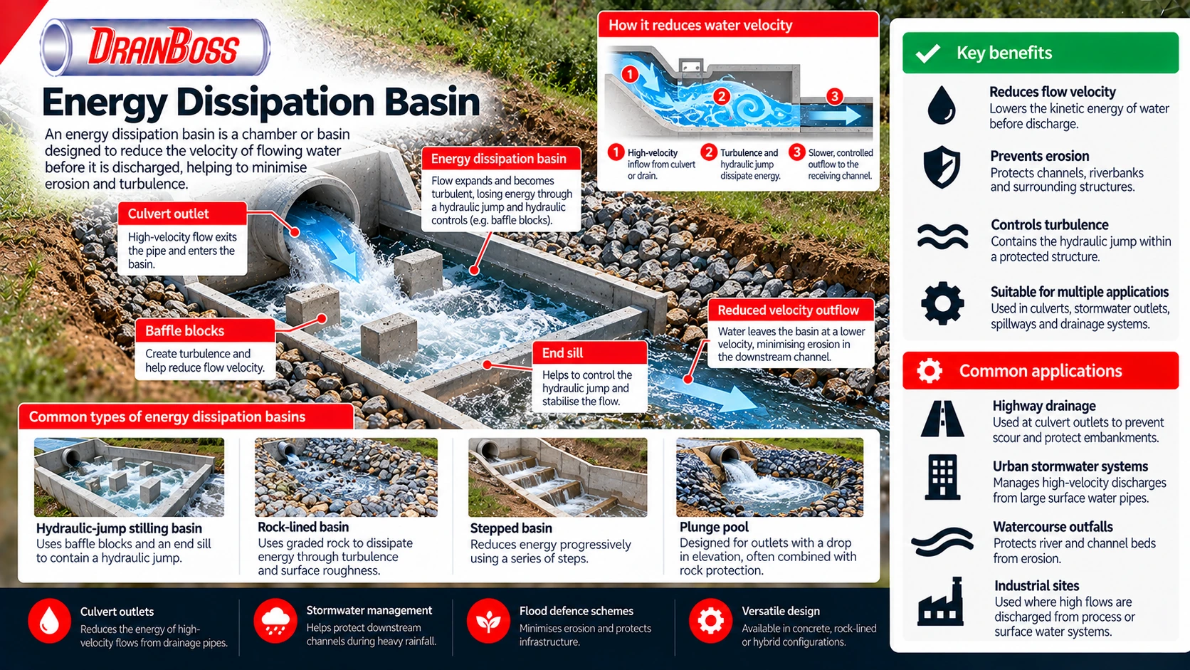
How an Energy Dissipation Basin Reduces Water Velocity
The operation of an energy dissipation basin is based on converting part of the kinetic energy of moving water into turbulence and other forms of energy loss. As water passes through the structure, its flow pattern changes, and the energy available to cause erosion downstream is reduced.
A common application involves water leaving a culvert or drainage pipe at relatively high velocity. The confined flow enters a wider or specially shaped basin, where it may expand, encounter hydraulic controls or undergo a hydraulic jump. The resulting turbulence dissipates energy within a controlled area instead of allowing it to act directly on the receiving channel.
A hydraulic jump occurs when rapidly flowing, shallow water transitions to a deeper, slower flow condition. This is a characteristic change from supercritical to subcritical flow and is accompanied by substantial turbulence, surface disturbance and energy loss.
In an appropriately designed stilling basin, the hydraulic jump can be contained within a protected concrete structure. The basin floor, walls and downstream transition are designed to withstand the resulting hydraulic forces and prevent erosion around the structure.
Not every energy dissipation basin relies on a hydraulic jump. Some arrangements use rock-filled areas, stepped surfaces, impact structures or changes in channel geometry to reduce velocity and distribute the discharge over a larger area.
The effectiveness of a basin depends on several interacting factors:
-
Inflow velocity and the depth of water entering the basin.
-
Peak discharge and the range of flows expected during operation.
-
Downstream water level, commonly described as tailwater.
-
Basin length, width and floor elevation.
-
Hydraulic controls such as baffle blocks, chute blocks and end sills.
-
Resistance of the basin lining to turbulence, impact and abrasion.
-
Stability of the outlet transition and receiving channel.
The downstream water level is particularly important for basins designed to contain a hydraulic jump. If the tailwater is too low, the jump may move beyond the protected basin, exposing the downstream channel to high velocities. Excessive tailwater can also alter the intended flow conditions and affect hydraulic performance.
For this reason, a basin cannot be designed solely from the diameter of the incoming drainage pipe. The receiving channel and the water levels that occur during different flow events must also be considered.
Hydraulic Design: Discharge, Velocity and Froude Number
The hydraulic design of an energy dissipation basin begins with the expected flow conditions at its inlet. Engineers determine the design discharge, flow depth, velocity and the characteristics of the downstream channel. These values are then used to assess the amount of energy that must be dissipated.
For a given flow rate, the average velocity is related to the cross-sectional area through the continuity equation:
Where:
-
\(Q\) is the discharge in cubic metres per second (m³/s).
-
\(A\) is the flow cross-sectional area in square metres (m²).
-
\(V\) is the average flow velocity in metres per second (m/s).
For example, if a drainage outlet conveys 0.6 m³/s through a flowing cross-sectional area of 0.2 m², the average velocity is 3 m/s. The actual flow conditions at an outlet may be more complicated, particularly where a pipe is partially full or the discharge forms a jet.
Velocity is important because the kinetic energy per unit mass of flowing water is proportional to the square of its velocity. In hydraulic calculations, velocity head is expressed as:
Here, \(g\) represents gravitational acceleration, approximately 9.81 m/s².
At a velocity of 3 m/s, the velocity head is approximately 0.46 m. At 6 m/s, it increases to approximately 1.83 m. Doubling the velocity therefore produces four times the velocity head, demonstrating why high-speed outlets can require substantial energy dissipation measures.
Another important design parameter is the Froude number. For a rectangular open channel, it can be expressed as:
Where \(y\) is the flow depth.
The Froude number indicates the relationship between flow inertia and gravitational effects. It is used to distinguish different open-channel flow regimes and assess the potential for a hydraulic jump.
| Froude number | Flow classification | Hydraulic significance |
|---|---|---|
| Fr less than 1 | Subcritical | Relatively deep, slower flow controlled strongly by downstream conditions |
| Fr equal to 1 | Critical | Transitional condition between subcritical and supercritical flow |
| Fr greater than 1 | Supercritical | Relatively shallow, rapid flow that may undergo a hydraulic jump |
| High supercritical values | Strongly supercritical | May require substantial energy dissipation and carefully designed hydraulic controls |
For channels that are not rectangular, the hydraulic depth is used rather than simply substituting the physical water depth into the rectangular-channel expression.
In a rectangular channel, the relationship between the water depths before and after an ideal hydraulic jump can be calculated using the sequent-depth equation:
Here, \(y_1\) is the incoming supercritical flow depth, \(y_2\) is the downstream conjugate depth and \(Fr_1\) is the upstream Froude number.
This relationship helps estimate the depth needed to support a hydraulic jump. It does not, by itself, determine the complete dimensions of a practical stilling basin, because basin geometry, tailwater variation, turbulence and hydraulic controls must also be assessed.
For major drainage structures, hydraulic design may involve established design procedures, physical modelling or computational hydraulic analysis. The appropriate method depends on the scale of the project, the complexity of the flow and the consequences of failure.
Types of Energy Dissipation Basins and Outlet Arrangements
Energy dissipation structures are not all constructed in the same way. Their configuration depends on whether the incoming water is discharged from a pipe, open channel, culvert, spillway or other hydraulic structure.
A conventional concrete stilling basin is commonly associated with high-energy open-channel flow. It provides a protected area in which a hydraulic jump can develop, with the basin geometry selected to contain the turbulent flow.
Some stilling basins incorporate chute blocks near the entrance. These features interact with the incoming flow and influence the formation of the hydraulic jump. Baffle blocks may be positioned further downstream to increase resistance and help dissipate energy.
An end sill is a raised feature located near the downstream end of certain basins. It can help control the outlet flow and support the required hydraulic conditions. The size and arrangement of these features must follow a suitable hydraulic design rather than being selected arbitrarily.
Rock-lined dissipation basins provide another approach. They use appropriately sized and placed rock to resist erosion while allowing water to lose energy through turbulence and interaction with the rough surface.
Rock protection is commonly used at culvert outlets and surface water drainage discharges where the expected velocities and site conditions make this approach suitable. It may be more economical than a large concrete structure, but its performance depends on correct rock sizing, layer thickness, foundation preparation and protection against undermining.
Other configurations include:
-
Hydraulic-jump stilling basins designed to contain the transition from supercritical to subcritical flow.
-
Impact basins that use a structural element to intercept and redirect incoming flow.
-
Rock-lined basins or aprons that dissipate energy through surface roughness and turbulence.
-
Stepped structures that reduce energy progressively along a descending flow path.
-
Plunge pools designed to accommodate water falling from an elevated outlet or spillway.
-
Specialised outlet structures combining expansion chambers, baffles and downstream protection.
These arrangements are not interchangeable. An impact basin may be suitable for a particular pipe discharge, while a conventional hydraulic-jump basin may be required for a large spillway or open-channel installation.
Similarly, a rock apron is not necessarily equivalent to a fully engineered stilling basin. A rock apron primarily provides erosion protection and may dissipate some energy, whereas a stilling basin may be designed specifically to establish and contain a particular hydraulic flow condition.
The choice depends on the expected hydraulic performance rather than the appearance or material of the structure.
Energy Dissipation at Culvert and Stormwater Outlets
Culvert outlets are among the most common locations where energy dissipation measures are required. A culvert conveys water beneath a road, railway, embankment or other obstruction, and the flow emerging from its outlet may have sufficient velocity to erode the receiving channel.
The risk is particularly significant where a culvert has a steep gradient or where water passes from a relatively smooth pipe into an unlined earth channel. The transition can produce local scour immediately downstream of the outlet.
Scour occurs when moving water removes material from the bed or banks of a channel. If the process continues, the resulting erosion can extend beneath a headwall, expose pipe foundations or destabilise nearby infrastructure.
An energy dissipation basin provides a controlled transition between the culvert and the downstream channel. Its design must consider the discharge characteristics at the outlet and the resistance of the receiving ground.
In some cases, a properly designed rock-lined apron may provide adequate protection. Where the discharge is more energetic or the consequences of erosion are greater, a more substantial basin may be necessary.
Stormwater systems present similar challenges. Large-diameter surface water pipes can convey significant flows during intense rainfall, especially where runoff is collected from extensive paved areas.
When this water is discharged into a ditch, stream or attenuation system, the outlet arrangement must prevent unacceptable erosion. Energy dissipation may therefore form part of a wider surface water management design that includes flow controls, storage structures and downstream channel protection.
An energy dissipation basin does not necessarily reduce the total volume of water discharged. Its principal purpose is to reduce the destructive effects of the flow by managing velocity and energy.
This distinguishes it from a detention or attenuation basin, which is primarily intended to store runoff temporarily and control the rate at which water leaves the site.
The two functions can be combined within a drainage scheme, but they should not be confused. An attenuation basin may still require a separate energy dissipation arrangement at an inlet or outlet where concentrated flow could cause erosion.
Structural Design, Erosion Protection and Sediment Management
The hydraulic performance of an energy dissipation basin must be supported by a structure capable of resisting the forces generated during operation. Water flowing through a basin can produce substantial turbulence, fluctuating pressures and localised impact forces.
Concrete basins require suitable structural design, foundations and reinforcement where applicable. The basin floor and walls must withstand hydraulic loading and the effects of the surrounding ground.
Uplift pressure can be an important consideration where groundwater or water beneath the basin acts against the underside of the structure. Drainage arrangements, foundation conditions and structural weight may all influence the design.
Abrasion is another potential problem. Stormwater and river flows may carry sand, gravel and other sediment that can wear exposed surfaces over time. The severity depends on sediment concentration, particle size, flow velocity and the materials used in the structure.
For rock-lined basins, stability depends on the ability of the selected rock to resist movement under the expected hydraulic forces. Undersized stone can be displaced during high flows, exposing the underlying soil to erosion.
The protection layer must also prevent the loss of finer foundation material through the spaces between larger stones. Depending on the design, this may require a properly graded granular filter or a suitable geotextile separation layer.
The downstream transition is often one of the most vulnerable parts of an installation. Even when the basin itself performs correctly, erosion may develop immediately beyond the protected area if water leaves at a velocity that exceeds the resistance of the receiving channel.
For this reason, designers must consider the extent of protection required downstream rather than treating the basin outlet as the end of the hydraulic problem.
Sediment behaviour also affects performance. Energy dissipation structures create zones of turbulence and changing velocity, which can influence where suspended material is deposited.
Some basins may accumulate sediment, particularly during lower-flow conditions or where the incoming water carries a substantial sediment load. Excessive deposits can alter the effective basin geometry and interfere with the intended hydraulic behaviour.
A basin designed to contain a hydraulic jump may perform differently if sediment significantly reduces its depth or obstructs hydraulic controls. This makes sediment management an operational consideration as well as a construction issue.
Where the structure is accessible for maintenance, the design should allow accumulated material to be removed without damaging the lining, floor or hydraulic features.
Inspection and Maintenance of Energy Dissipation Basins
Energy dissipation basins are exposed to changing flow conditions and may experience long periods of low activity followed by intense hydraulic loading during storms. Their condition should therefore be assessed in relation to the events they are designed to accommodate.
Routine inspection can identify sediment accumulation, displaced rock, damaged concrete, blocked outlets and developing erosion. Additional inspections after significant rainfall or flood events may be necessary where high flows could have affected the structure.
The most important maintenance concerns are those that change the hydraulic geometry or reduce the stability of the protected area.
Typical inspection points include:
-
Sediment or debris obstructing the basin entrance or outlet.
-
Displaced baffle blocks, damaged end sills or other altered hydraulic features.
-
Cracking, spalling or abrasion of concrete surfaces.
-
Movement or loss of rock protection.
-
Erosion around the basin edges or downstream transition.
-
Settlement or void formation beneath structural elements.
-
Vegetation growth that obstructs the intended flow path.
-
Evidence of overtopping, bypass flow or erosion outside the designed channel.
Not every accumulation of sediment indicates a defect. The significance depends on the basin design, the expected sediment load and whether the deposits interfere with hydraulic performance.
Similarly, some surface wear may be consistent with the operating environment. More serious deterioration includes exposed reinforcement, displaced structural components, undermining and changes that allow high-energy flow to bypass the protected area.
Where repeated erosion occurs downstream, adding more rock without reassessing the hydraulic conditions may provide only temporary improvement. The problem may involve inadequate protection length, incorrect stone sizing, unexpected discharge conditions or tailwater levels that differ from those assumed during design.
Maintenance work must also consider the hazards associated with drainage infrastructure. Basins may contain deep water, slippery surfaces, unstable sediment or confined spaces within connected structures. Access arrangements and working methods should reflect the actual site conditions.
Energy Dissipation Basin Design in UK Drainage Projects
In the United Kingdom, energy dissipation basins may form part of highway drainage schemes, flood alleviation works, watercourse improvements and surface water drainage infrastructure. Their design is influenced by the intended hydraulic function, site constraints and the requirements of the relevant approving authorities.
For highway projects, outlet protection may be required where culverts or drainage pipes discharge into roadside ditches, channels or natural watercourses. The design must account for the expected runoff, local topography and the consequences of erosion near the highway.
Flood management schemes may involve larger energy dissipation structures associated with control gates, spillways or engineered channels. In these situations, hydraulic performance can be critical to the safety and reliability of the wider infrastructure.
Where a drainage outlet connects to an ordinary watercourse or main river, proposed works may require consent or permits from the relevant authority. The applicable requirements depend on the location, nature of the works and the regulatory arrangements in the relevant part of the UK.
Environmental considerations may also affect the design. High-velocity discharges can damage channel habitats, disturb sediment and cause local erosion. A properly designed outlet can help manage these impacts, although energy dissipation alone does not address every ecological concern.
The receiving watercourse should therefore be considered as part of the overall drainage system. Its bed material, bank stability, seasonal water levels and expected flood conditions influence the choice of outlet protection.
Energy dissipation is especially important where concentrated runoff enters a channel that previously received water more gradually. New developments, altered drainage routes and increased impermeable surfaces can change the volume and timing of runoff reaching an outlet.
A basin must be designed for the expected range of hydraulic conditions rather than a single convenient flow rate. Lower flows, peak design events and elevated downstream water levels may produce different flow patterns within the same structure.
The design process should establish whether the proposed basin can contain the intended energy dissipation mechanism and whether the downstream channel remains stable after discharge. Where these conditions cannot be achieved within the available space, an alternative outlet arrangement or broader drainage redesign may be required.
A successful energy dissipation basin transfers the potentially damaging hydraulic effects of a concentrated discharge into a structure specifically designed to withstand them. Its effectiveness ultimately depends on the relationship between inlet energy, basin geometry, downstream water levels and the resistance of the receiving channel.