
What is a Foundation Drain
A foundation drain is a drainage system installed around or beneath a building’s foundations to collect groundwater and direct it away from the structure. It helps reduce water accumulation against foundation walls, basement walls and other below-ground construction. In the UK, this arrangement is commonly associated with perimeter drainage, land drains or French drains, although these terms do not always describe identical installations.
A typical foundation drain consists of a perforated pipe surrounded by free-draining aggregate, often separated from the surrounding soil by a suitable geotextile filter. Water enters the drainage layer, passes into the pipe and is conveyed towards an appropriate discharge point. The system must be designed around ground conditions, foundation depth, groundwater behaviour and the availability of a reliable outlet.
Foundation drainage is particularly relevant to buildings with basements, retaining walls or foundations exposed to persistent groundwater. However, it is not a substitute for structural waterproofing where a below-ground space must remain dry. Its purpose is to manage water around the building and, where conditions permit, reduce the hydraulic pressure acting on below-ground structures.
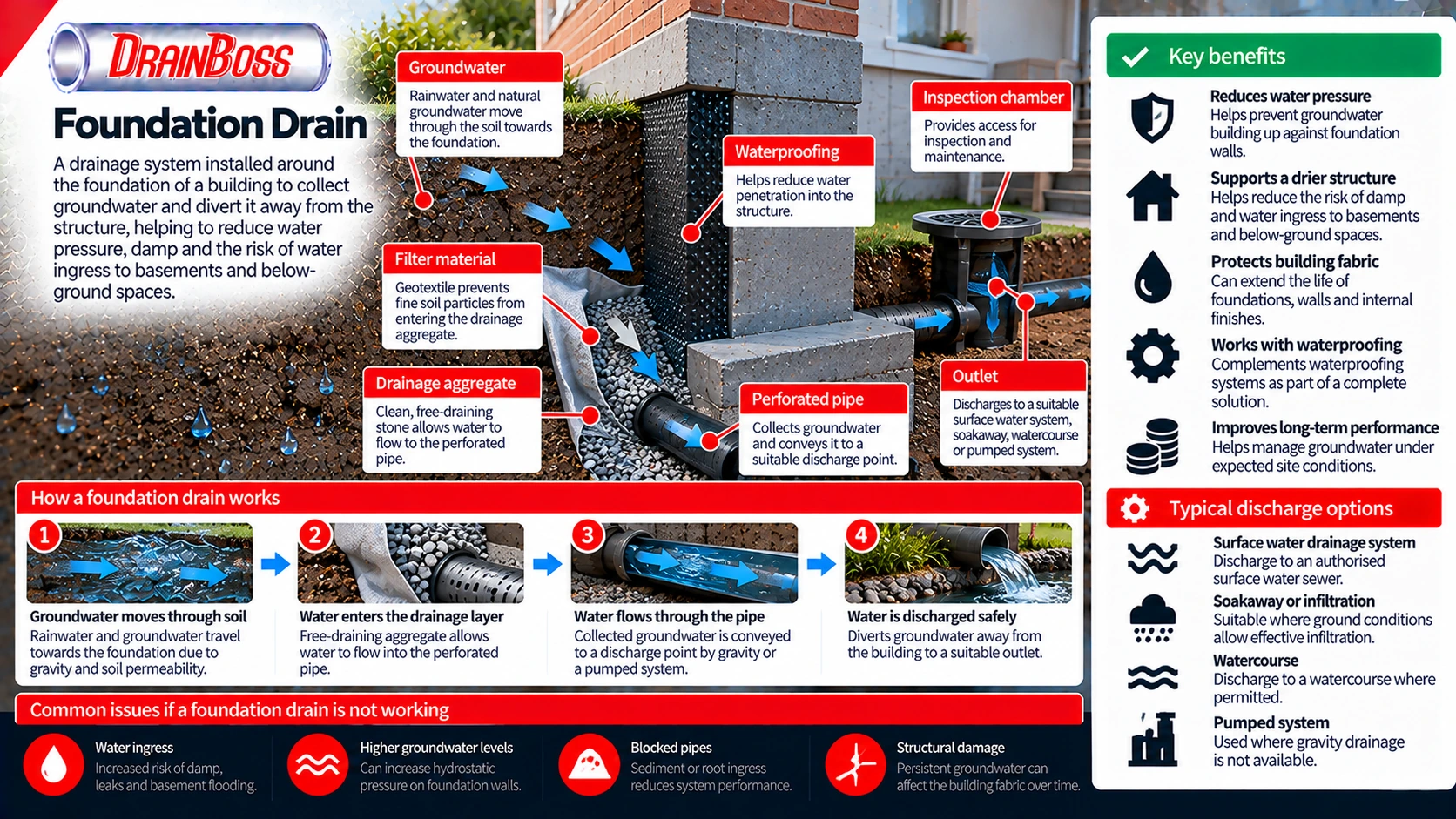
How a Foundation Drain Collects Groundwater
Water reaches building foundations through several mechanisms. Rainfall can infiltrate the ground and move downwards through permeable soil, while groundwater may travel laterally through soil layers towards an excavation or basement wall. The movement depends on soil permeability, groundwater levels, ground gradients and the presence of less permeable layers.
Excavations around foundations are often backfilled with material that differs from the surrounding natural ground. If this backfill is more permeable, water may move through it more readily and collect near the foundation. Without an effective drainage route, the water can remain against basement walls or accumulate at the base of the excavation.
A foundation drain provides a preferential route for this water to leave the area. The aggregate surrounding the pipe allows groundwater to move towards the drainage system, while openings in the pipe admit water for conveyance downstream. The effectiveness of this arrangement depends on the permeability of the surrounding materials and the hydraulic level at the outlet.
A conventional perimeter foundation drain may include:
-
Perforated drainage pipe, commonly manufactured from suitable plastic materials.
-
Clean, free-draining aggregate surrounding the pipe.
-
Geotextile filtration to limit the migration of fine soil particles into the drainage layer.
-
Inspection or access points for checking and maintaining the system.
-
A suitable outlet, such as an approved surface water drainage connection or a properly designed infiltration arrangement.
-
Waterproofing and protective layers on the foundation wall where required by the building design.
The perforated pipe is normally positioned near the foundation base, with its exact level determined by the structural and waterproofing design. It must not be installed in a way that undermines the foundation or removes support from the surrounding ground. Drainage trenches excavated beside existing buildings require particular care because they can affect soil stability and foundation bearing conditions.
Foundation drains generally operate by gravity. Water entering the pipe travels towards the outlet according to the available hydraulic gradient, although a pumped arrangement may be necessary where gravity discharge is unavailable. A pipe that has no effective discharge route cannot reliably lower water levels around the building.
Foundation Drain Installation and Pipe Arrangement
The layout of a foundation drainage system depends on whether it is being incorporated into a new building or retrofitted around an existing structure. New construction usually provides better access to foundation walls and allows the drainage, waterproofing and backfill arrangements to be designed together. Retrofitting may involve restricted excavation space, existing services and uncertainty about the depth or condition of the foundations.
For perimeter drainage, the pipe is commonly installed in a trench containing graded drainage aggregate. A suitable geotextile may separate the aggregate from surrounding fine-grained soil, reducing the risk of particles entering and obstructing the drainage layer. The filter arrangement must be compatible with the ground conditions because an unsuitable geotextile can itself become clogged.
The pipe diameter is selected according to the expected inflow, available gradient, maintenance requirements and outlet capacity. Nominal diameters around 100 mm are commonly encountered in small land drainage applications, but this is not a universal requirement for foundation drains. Larger buildings or sites with substantial groundwater inflows may need different pipe sizes, additional collection runs or a more complex drainage arrangement.
Pipe gradient is another important consideration. The installation must provide a practicable route for collected water to reach the discharge point without unnecessary low spots that encourage sediment accumulation. There is no single minimum gradient that can be applied to every foundation drain regardless of pipe type, soil conditions and system configuration.
The table below identifies the principal components and the problems associated with unsuitable installation.
| Component | Main function | Potential problem |
|---|---|---|
| Perforated pipe | Collects and conveys groundwater | Blockage, deformation or insufficient capacity |
| Drainage aggregate | Allows water to move towards the pipe | Contamination by soil fines |
| Geotextile filter | Limits migration of fine particles | Clogging or incorrect filter selection |
| Foundation waterproofing | Restricts water penetration into the structure | Leakage through damaged or incomplete protection |
| Inspection access | Allows examination and maintenance | Inaccessible pipework |
| Outlet connection | Removes collected groundwater | Backwater, restriction or unavailable discharge |
| Sump and pump, where installed | Lifts water when gravity discharge is unavailable | Pump failure or loss of electrical supply |
The arrangement of pipe perforations also depends on the drainage product and design. Perforated pipes may have openings distributed around part or all of their circumference, and the correct orientation should follow the manufacturer’s instructions and the intended hydraulic arrangement. Installation details should not be transferred indiscriminately between different pipe products.
Where foundation drainage is installed beside a basement wall, the wall may also have a drainage or protection layer that directs water downwards towards the perimeter drain. Such layers must be compatible with the waterproofing system and properly terminated. Poor detailing at wall-to-floor junctions, service penetrations and changes in level can allow water to bypass otherwise effective protection.
Foundation Drainage and Basement Waterproofing
Foundation drainage and basement waterproofing perform related but different functions. Drainage attempts to collect and remove groundwater, while waterproofing provides resistance to water entering the structure. A building may require both, particularly where below-ground accommodation must remain dry.
In the UK, BS 8102:2022 provides guidance on protecting below-ground structures against water ingress. It recognises different approaches to waterproofing, including barrier protection, structurally integral protection and drained cavity protection. The appropriate strategy depends on the intended use of the below-ground space, the required internal environment and the assessed water risk.
A foundation drain located outside the building is not automatically equivalent to a Type C drained cavity waterproofing system. Type C protection generally manages water that enters a controlled cavity within the waterproofing arrangement and directs it towards a suitable drainage and discharge system. An external perimeter drain instead aims to intercept groundwater before it accumulates against the structure.
The distinction matters because an external drain can become obstructed, lose its outlet or be overwhelmed by groundwater. If the building relies entirely on that drain to remain dry, failure may expose the structure to water pressures that were not adequately considered.
Groundwater pressure increases with the height of water acting against a structure. As an illustration, a 2 m column of water produces a hydrostatic pressure of approximately 19.6 kPa at its base, equivalent to 19.6 kN per square metre. This assumes freshwater and a static condition, and it does not account for other loads acting on the wall.
A functioning drainage system may reduce the water head against the structure under suitable conditions. However, the designer should not assume that groundwater pressure will always be eliminated, particularly where the surrounding soil has low permeability or the outlet may become submerged.
Below-ground waterproofing should therefore be selected through a risk-based design process rather than relying on the presence of a perforated drain alone.
Where Foundation Drains Discharge Water
The outlet is one of the most important parts of a foundation drainage system. Collecting groundwater without providing a reliable discharge route can leave water accumulating within the drainage trench. In some circumstances, this can worsen local saturation rather than improve it.
The available options depend on site levels, soil permeability, drainage infrastructure and legal requirements. A gravity outlet may be possible where a suitable receiving system is located below the drain, while a sump and pump may be necessary where the receiving point is higher.
Potential discharge arrangements include:
-
A suitable infiltration system, where ground conditions, separation distances and groundwater levels allow effective infiltration.
-
An authorised connection to a surface water drainage system, subject to the relevant approvals and capacity requirements.
-
A permitted discharge to a watercourse, where the location and regulatory conditions allow it.
-
A collection sump with pumping equipment, where gravity drainage is not practicable.
Connection to a foul sewer should not be assumed acceptable. In England and Wales, the discharge of groundwater into public sewerage infrastructure can require the sewerage undertaker’s consent, and the suitability of the receiving system must be established. Local requirements and the applicable legal framework should be checked before connecting the drain.
A soakaway is not necessarily suitable simply because there is space available on the site. Infiltration performance depends on the permeability of the surrounding ground and the level of groundwater. A poorly located soakaway can also return water towards the foundations it is intended to protect.
Pumped systems introduce additional operational requirements. The sump must have suitable capacity, and the pump must be capable of handling the expected inflow and discharge head. Where pump failure would create a significant flooding risk, alarm arrangements, backup provision and maintenance access may be necessary.
Backwater must also be considered. A gravity outlet connected to a drainage system that becomes surcharged may be unable to discharge during heavy rainfall. Depending on the connection and hydraulic conditions, water may also move towards the foundation drainage system unless suitable protection is provided.
Soil Conditions, Groundwater and Drainage Performance
The performance of a foundation drain depends heavily on the ground surrounding it. Sandy and gravelly soils generally allow water to move more readily than clay-rich soils, although actual permeability varies considerably within each soil category. A drain that works effectively in permeable ground may have a much smaller influence on groundwater levels in low-permeability clay.
Layered ground can create additional complications. Water may move through a permeable layer until it encounters a less permeable stratum, producing perched groundwater above that boundary. A foundation excavation intersecting the permeable layer can become a collection point for this water.
Seasonal groundwater variation must also be considered. Groundwater levels can rise after prolonged wet weather, and a site that appears dry during construction may experience substantially different conditions in winter. Assessing only the groundwater observed on one day may therefore underestimate the drainage requirements.
Drainage systems can also alter local groundwater movement. Where a drain intercepts substantial groundwater flow, its influence may extend beyond the immediate foundation trench. In sensitive ground conditions, changes in groundwater levels can affect neighbouring structures, soil behaviour or existing drainage arrangements.
For this reason, foundation drainage should not be treated as a routine excavation detail on every site. Ground investigation and engineering assessment may be necessary where groundwater conditions are uncertain, foundations are deep or nearby structures could be affected.
The relationship between the drain and the foundation is particularly important in existing buildings. Excavating below the underside of a shallow foundation can remove supporting ground and create a risk of movement or structural damage. A drainage trench should never be deepened beside an existing foundation without considering its structural implications.
Blockages, Inspection and Foundation Drain Maintenance
Foundation drains are buried systems, and problems may remain unnoticed until water begins accumulating near the building. Unlike an exposed gutter or channel drain, the perforated pipe and surrounding aggregate cannot usually be inspected visually without access points or excavation. This makes suitable inspection provision important during installation.
Sediment is a common source of deterioration. Fine particles can enter the drainage layer, accumulate within the pipe or reduce the permeability of the surrounding aggregate. Root intrusion may also occur where roots reach defective joints or other accessible openings.
A blocked foundation drain does not always produce an immediate visible leak. The effects depend on groundwater conditions, waterproofing performance and the location of the restriction. Possible warning signs include persistent dampness at low-level walls, recurring basement water ingress or standing water in accessible drainage chambers.
However, these symptoms are not specific to foundation drainage failure. Water penetration may result from defective waterproofing, leaking service pipes, surface water entering at openings or condensation within the building. Investigation should establish the source before recommending excavation or drainage replacement.
Where accessible, CCTV inspection may help identify pipe deformation, sediment deposits or root intrusion. Cleaning can sometimes restore the pipe’s capacity, but it may not correct a drainage layer that has become contaminated with fine soil. High-pressure cleaning must be appropriate for the pipe material and condition to avoid damage.
Maintenance also includes checking the discharge point. A clear perforated pipe will not function as intended if its outlet is obstructed, submerged or disconnected. Pumped systems require additional checks of pumps, controls, alarms and electrical equipment.
Foundation drains are most effective when designed as part of a complete groundwater management strategy. Pipe layout, filtration, structural safety, waterproofing and outlet performance all influence whether collected water can be removed reliably. The critical requirement is not simply installing a perforated pipe beside the foundations, but ensuring that groundwater has a safe, maintainable route away from the building under the conditions the site is expected to experience.